STANDARD REFERENCES
In this brochure, Jianzhi brand threaded pipe fittings in malleable cast iron conform to the international IOS49 and the European EN 10242 standards.
The connecting threads conform to the international ISO 7-1 and to the European EN 10226.
The material used is high quality blackheart malleable cast iron in accordance with the requirements of EN 1562: EN-GJMB-350-10 (ISO5922).
These products are primarily used in installations connected to water, gas, oil, and other fluid systems. The main function of these fittings is to connect pipes or to change the direction of fluid flow.
1. Required characteristics
1.1 Permissible working pressure and temperature
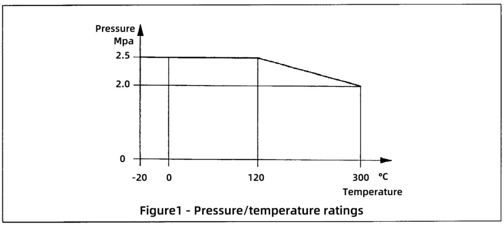
Fittings of all sizes are required to be suitable for maximum permissible working pressures within the temperature ranges specified in Table 1. Intermediate pressure ratings at temperatures between 120°C and 300°C shall be obtained by linear interpolation. The lowest service temperature for fittings is -20 degrees Celsius in normal applications.
It is recommended to consult the manufacturer for special applications at temperatures below -20°C.
1.2 Design strength
Pressure-containing fittings including the component parts of unions shall be designed to withstand the design test pressures given in Table 2. Each size of the fitting shall be type tested in accordance with Table 2

| Service temperature °C | Maximum permissible working pressure Mpa |
| -20 to 120 | 2.5 |
| 120 to 300 | Interpolated values |
| 300 | 2.0 |
Hydrostatic design test pressure (gauge) Sizes 1/8 to 4 Sizes 5 and 6 10 Mpa 6.4 Mpa
Table 2 - Design test pressures 2. Surface layer
Black or galvanized (hot dip zinc coating) fittings are available. And the zinc coating meet the following requirements. If the customer need a special protective layer to protect against superficial rust, the requests is also applied.
2.1 Chemical composition of the zinc coating
The content by mass of the accompanying elements in the finish zinc coating does not exceed the following maximum values:
| Aluminium (Al) | 0.1% |
| Antimony (Sb) | 0.01% |
| Arsenic (As) | 0.02% |
| Bismuth (Bi) | 0.01% |
| Cadmium (Cd) | 0.01% |
| Copper (Cu) | 0.1% |
| Lead (Pb) | 1.6%, in individual cases 1.8% |
| Tin (Sn) | 0.1% |
2.2 Coating mass per surface unit
The surface related mass of the zinc coating does not less than 500 g/㎡, as an average of 5 fittings. This corresponds to a medium layer thickness of 70μm.It does not less than 450 g/㎡(63μm)when it is measured on an individual sample.

where

is the medium layer thickness of the zinc coating in μm.

is the surface related mass of the zinc coating in g/㎡.
2.3 Surface condition of the zinc coating
The zinc coating on the internal surface of the fitting is continuous, with the exception of machined black surfaces.In the special case of larger material cross-sections the iron-zinc alloy phases may grow through. The internal zinc coating are free from zinc blisters, zinc burrs, non-metallic remainders.
3 Dimensions and tolerances
The main dimensions of the pipe fittings are given in the product specification and dimension table on the following pages. If the size is not specified, the manufacturer shall negotiate with the purchaser. Where maximum or minimum dimensions are not specified, the tolerances for face-to-face and face-to-centre dimensions of pipe fittings are as given in Table 3.
| Dimension | ≤30 | >30~≤50 | >50~≤75 | >75~≤100 | >100~≤150 | >150~≤200 | >200 |
| Tolerance | ±1.5 | ±2.0 | ±2.5 | ±3.0 | ±3.5 | ±4.0 | ±5.0 |
NOTE:
- Fittings sizes shown in brackets are optional sizes and which may have a limited availability.
- The face-to-face and face-to-centre dimensions of unions may not always comply with the tolerance given due to the compound effect of piece tolerances and design upon the final assembly.
Laying lengths are given for assistance and guidance during installation. Their accuracy is dependent upon the tolerances given in 7.1 and on the tolerance of the threads specified in ISO 7-1 (or EN10226).
4 Threads
4.1 Choice of thread
4.1.1 Jointing thread
Fittings shall be threaded in accordance with ISO7-1 (Or EN10226).
4.1.2 Fastening threads
The threads of backnuts, union nuts and their mating threads shall be in accordance with ISO 228-1 (Or ENISO228).
4.2 Alignment of threads
The axes of the screw threads are accurate within ±0.3°of the specified angle.
4.3 Chamfering
The outlets of the fittings shall have a chamfer.
On internal threads, the chamfer has a minimum included angle of 90°, and the diameter at the face exceeds the major diameter of the thread.
On external threads, the chamfer should be a minimum included angle of 60° and the diameter at the face not exceed the minor diameter of the thread at that face.
4.4 Taper thread
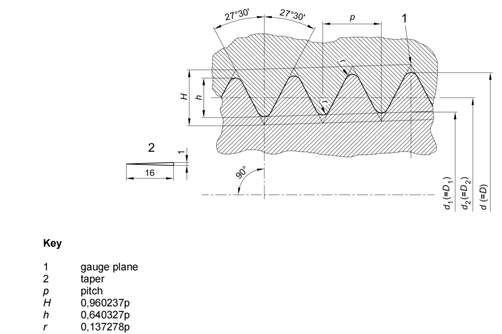
The basic form of the taper pipe thread is as shown in figure 2. The taper is 1 to 16, measured on the diameter. The angle between the flanks, measured in an axial plane section, is 55°, the flanks making equal angles with the axis.
The thread profiles are rounded off equally at crests and roots by circular arcs blending tangentially with the flanks in such a manner as to give the same thread height h as for parallel threads.

4.5 Parallel thread
The basic form of the parallel pipe thread is as shown in figure 3. The angle between the flanks, measured in an axial plane section, is 55°. The thread profiles are rounded equally at crests and roots by circular arcs blending tangentially with the flanks.

4.6 Thread lengths
4.6.1 External thread
The terms relating to the external taper pipe thread are given in figure 4.
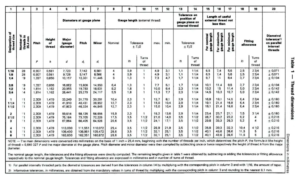
The length of the useful thread, allowable in practice, is the sum of the lengths of the complete and incomplete threads, excluding the washout thread. The minimum length of the useful thread must be not less than the minimum gauge length plus the fitting allowance.
4.6.2 Internal thread
The design of internally threaded parts are such that they can receive external threads up to the lengths given in column 16 of table 4. The minimum lengths Lmin of useful thread in the case of internal threads with free run-out shall be not less than 80 % of the values given in column 17 of table 4. (See figure 5.)


5. Leak tightness test
One of the following methods will be used for testing all pressure containing fittings (after they have been machinized, but before they are protected by any other protective coating other than zinc coating). As a result of this testing, each fitting must not show any signs of leakage. To ensure the authenticity of the test results, all test equipment is equipped with a qualified monitoring pressure gauge:
a) by the application of an internal hydrostatic pressure of not less than 2 MPa, test requirements are refer to table 5;
Pipe fittings dimensions (inch) Test time (s) Test result 1/8~2 ≥15 Each fitting must not show any signs of leakage or damage. 2½~6 ≥60
Table 5 - Test requirementsb) by the application of an internal pneumatic pressure of not less than 0.5 MPa, whilst the fitting is completely immersed in water or light oil;
c) by other tests which ensure an equivalent quality.
All Jianzhi brand fittings are satisfy an internal pneumatic pressure tightness test of 0.6 MPa, without any signs of leakage.

Related Products
