
Abstract
This exploration provides a comprehensive analysis of the fundamental role pipe fittings play within Heating, Ventilation, and Air Conditioning (HVAC) systems. It moves beyond a superficial listing of components to examine the intricate ways these fittings function as the critical connective tissue that enables the entire system to operate. The discourse delves into five principal applications: directing fluid flow in refrigerant and hydronic circuits, managing system pressure and fluid state, facilitating condensate drainage, enabling component connection and isolation for maintenance, and providing adaptability through threaded connections. A central theme is the examination of material properties, with a particular focus on malleable cast iron, and how these properties—such as strength, ductility, and corrosion resistance—directly impact system integrity, efficiency, and longevity. By analyzing the distinct functions of fittings like elbows, tees, reducers, and unions, the article illuminates how these seemingly minor parts are indispensable for controlling temperature, humidity, and air quality in built environments. The investigation synthesizes principles from fluid dynamics, materials science, and practical engineering to present a holistic understanding of how pipe fittings are used in HVAC systems, arguing that their proper selection and installation are paramount to achieving optimal performance and reliability.
Key Takeaways
- Fittings direct high-pressure refrigerant and water flow efficiently.
- Specialized fittings manage system pressure and fluid velocity.
- Proper drainage fittings prevent water damage and contamination.
- Unions and flanges are vital for system maintenance and repair.
- Understanding how pipe fittings are used in HVAC systems ensures longevity.
- Threaded connections offer versatility for system modifications.
- Material choice, like malleable iron, dictates system durability.
Table of Contents
- Introduction: The Unseen Architects of Indoor Climate
- 1. Directing the Flow: The Arterial Network of Refrigerant and Hydronic Lines
- 2. Managing System Pressure and Fluid State with Specialized Fittings
- 3. Ensuring Drainage and Condensate Removal: The System’s Excretory Function
- 4. Connecting and Isolating System Components for Maintenance and Repair
- 5. Adapting and Modifying Systems with The Language of Threaded Connections
- The Broader Context: Material Science, Durability, and the Wisdom of Choice
- Frequently Asked Questions About Pipe Fittings in HVAC
- Conclusion
- References
Introduction: The Unseen Architects of Indoor Climate
When we consider the marvel of a modern building’s climate control, our thoughts often gravitate towards the visible and the grand: the silent vents delivering cool air on a sweltering day, the thermostat on the wall that acts as our interface with comfort, or the large outdoor condenser unit humming quietly. We perceive the effects—the stable temperature, the pleasant humidity—but we seldom contemplate the intricate, hidden network that makes this comfort possible. This network, a complex circulatory system of pipes and ducts, relies on a category of components that are as foundational as they are overlooked: pipe fittings. To truly appreciate the engineering behind thermal comfort, we must look into the veins and arteries of the system, to understand how these small but mighty connectors are the true architects of our indoor environment.
Beyond the Vents: Why Pipe Fittings are the Nervous System of HVAC
Imagine an HVAC system as a living organism. The furnace or boiler is the heart, pumping life-giving heat, while the air conditioner or chiller is the lungs, providing the cool breath of relief. The ductwork and pipes are the circulatory system, the vessels that carry this thermal energy throughout the structure. If this analogy holds, then the pipe fittings—the elbows, tees, couplings, and unions—are the joints, the nerve ganglia, and the valves of this body. They are not passive connectors; they are active directors of flow, managers of pressure, and guarantors of integrity. Every change in direction, every split in the path, every transition in pipe size is governed by a specific fitting designed for that exact purpose. Without them, we would have only straight, disconnected lines, incapable of navigating the complex anatomy of a building or performing the thermodynamic cycles required for heating and cooling. A failure in a single, inexpensive fitting can compromise a multi-thousand-dollar system, leading to refrigerant leaks, water damage, or a complete loss of function. Therefore, a deep understanding of how pipe fittings are used in HVAC systems is not merely a technical curiosity; it is a fundamental aspect of designing, installing, and maintaining systems that are efficient, reliable, and safe.
A Matter of Material: Setting the Stage for Malleable Iron’s Role
The choice of material for these critical components is a profound decision, one that speaks to the anticipated lifespan and resilience of the entire HVAC installation. The fluids coursing through these pipes are often not benign. They can be high-pressure refrigerants undergoing phase changes, heated water or steam in hydronic systems, or corrosive condensate water. The fittings must withstand constant pressure, significant temperature fluctuations, and mechanical vibration. While materials like copper and PVC have their place, another material stands out for its unique combination of strength, durability, and workability: malleable cast iron. Produced through a meticulous process of heat treatment, malleable iron possesses a toughness that resists the shocks and stresses common in mechanical rooms, along with a pressure-retaining capability that is second to none in many applications. Whether in its natural black state or with a protective galvanized coating, malleable iron offers a robust solution for the demanding world of HVAC. As we delve into the specific applications of pipe fittings, we will see time and again how the physical properties of the material are inextricably linked to the function of the fitting itself, making the selection process a critical exercise in engineering judgment. The story of HVAC is, in large part, the story of the materials that contain and direct its power.
1. Directing the Flow: The Arterial Network of Refrigerant and Hydronic Lines
At the very core of any HVAC system’s function is the movement of a working fluid. This fluid acts as a courier, absorbing heat from one location and releasing it in another. In air conditioning and heat pump systems, this courier is a refrigerant; in boilers and chillers, it is typically water or a water-glycol mix. The network of pipes that carries this fluid is the system’s arterial network, and the pipe fittings are responsible for ensuring this network can be constructed within the physical constraints of a building, directing the flow precisely where it needs to go. This is perhaps the most intuitive but also one of the most critical roles of pipe fittings.
The High-Stakes World of Refrigerant Management
Let us first consider the refrigerant cycle, the magic behind modern air conditioning. This process involves a refrigerant changing between liquid and gas states at very specific pressures and temperatures. The pipework carrying this refrigerant—the “line set”—is a closed, sealed loop. A leak of refrigerant is not just an inconvenience; it is an environmental concern and a costly repair. The fittings in this loop must maintain absolute integrity under pressures that can exceed 300 pounds per square inch (psi). They must connect the indoor evaporator coil to the outdoor condenser coil, a path that is rarely a straight line. It must navigate around structural beams, through walls, and up or down multiple floors. This is where the humble pipe fitting demonstrates its profound importance. The system’s reliability is contingent upon the flawlessness of every single connection point within this high-pressure environment. A weak fitting is the system’s Achilles’ heel, a point of potential failure that undermines the entire operation.
Elbows and Bends: Navigating the Architectural Maze
The most common challenge in routing pipes is changing direction. This is the domain of the elbow fitting. Available in standard angles like 90 degrees and 45 degrees, elbows allow the installer to guide the pipework around obstacles with precision. Think of them as the anatomical joints—the knees and elbows—of the piping system. In a tight mechanical closet or when routing pipes along a ceiling, a series of elbows can create a path that would be impossible with rigid, straight pipe alone. For example, a 90-degree elbow can turn a vertical pipe run into a horizontal one, allowing it to pass through a wall. A 45-degree elbow can create a gentle offset to avoid a smaller obstruction. The choice between a standard (short-radius) elbow and a long-radius elbow is not merely aesthetic. A long-radius elbow creates a more gradual turn, which reduces frictional losses and pressure drop in the fluid. In a long and complex piping run, the cumulative effect of using long-radius elbows can lead to a measurable improvement in system efficiency, as the compressor or pump does not have to work as hard to push the fluid through the circuit. This is a clear instance where the geometry of the fitting has a direct impact on the energy consumption of the HVAC system.
Tees and Crosses: The Junctions of Thermal Energy
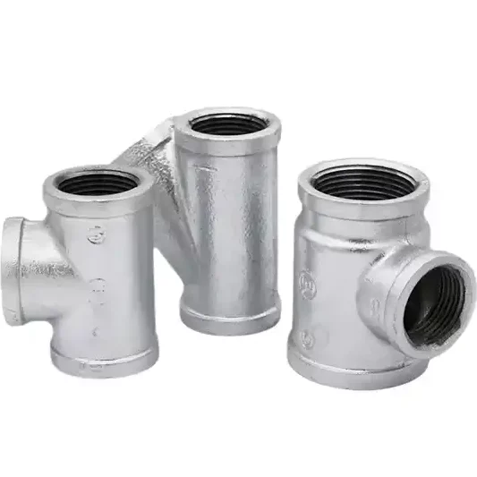
While elbows change direction, tees and crosses manage distribution. A tee fitting has three openings, allowing a single line to be split into two separate lines, or for two lines to merge into one. Imagine a large commercial building with a central chiller plant. A main chilled water supply line leaves the plant, and as it runs through the building, tee fittings are used to branch off smaller supply lines to serve the air handling units on each floor. The tee acts as a divergence point, distributing the cooling capacity of the central plant across the entire building. Conversely, in the return line, tees are used to merge the flow from each floor back into the main return pipe heading to the chiller. Cross fittings, with four openings, are less common but serve a similar purpose for more complex junctions. The proper sizing and placement of these fittings are critical. An improperly sized tee can create turbulence, noise, and an imbalanced flow, starving some parts of the system while over-supplying others. In hydronic heating systems, tees are fundamental to creating the primary-secondary pumping loops that allow for sophisticated zone control. For any professional involved in HVAC, understanding the application of these junction fittings is essential for designing a balanced and effective distribution network. The full range of malleable cast iron parts provides the necessary components for building these complex networks with confidence.
The Critical Role of Pressure Integrity in Refrigerant Lines
Returning to refrigerant lines, the material of the fitting is of paramount importance. While copper is often used and joined by brazing, threaded malleable iron fittings offer an alternative known for exceptional mechanical strength. Brazing requires a high degree of skill and care to create a leak-proof joint. A poorly made braze can crack under the vibration of the compressor or due to thermal expansion and contraction. Threaded malleable iron fittings, when properly sealed with an appropriate thread sealant, create a joint of immense strength and reliability. The NPT (National Pipe Thread Taper) or BSPT (British Standard Pipe Taper) threads create a mechanical seal that tightens as the fitting is wrenched, with the sealant filling any microscopic voids. This method is particularly advantageous in applications with high vibration or where future disassembly might be required. The inherent strength of malleable iron makes it highly resistant to being over-torqued or cracked during installation, a common issue with less robust materials. For gas lines, such as natural gas or propane feeding a furnace, threaded black pipe fittings made of malleable iron are often the mandated standard by building codes precisely because of this proven pressure integrity and mechanical robustness.
2. Managing System Pressure and Fluid State with Specialized Fittings
Beyond simply directing the path of the fluid, pipe fittings play a sophisticated role in actively managing the physical properties of that fluid—specifically its pressure and velocity. This is not a passive consequence of their presence but an intentional application of fluid dynamic principles. The shape, size, and type of fitting are chosen to manipulate the flow in ways that are essential for the thermodynamic cycle to function correctly and efficiently. This demonstrates a more advanced understanding of how pipe fittings are used in HVAC systems, moving from routing to regulation.
Reducers and Expanders: Controlling Velocity and Pressure
A reducer fitting, as its name suggests, connects a larger pipe to a smaller one. This seemingly simple function has profound implications for the fluid within. According to the principle of continuity in fluid dynamics, for an incompressible fluid like water, a reduction in the cross-sectional area of the pipe must be accompanied by an increase in the velocity of the fluid. Conversely, an expander (or an enlarging reducer) increases the pipe diameter, causing the fluid’s velocity to decrease. This change in velocity is directly linked to a change in pressure, as described by Bernoulli’s principle. When velocity increases in the smaller pipe, kinetic energy increases, and potential energy, in the form of pressure, decreases. This principle is harnessed throughout HVAC systems. For example, a reducer might be used just before a control valve to ensure the fluid is moving at the optimal velocity for the valve to operate accurately. In a refrigerant line, controlling velocity is critical. If the velocity of the refrigerant gas returning to the compressor is too low, the oil that circulates with the refrigerant might not be carried along effectively, potentially starving the compressor of lubrication—a catastrophic failure. Reducers are used to maintain a minimum velocity in vertical risers to ensure proper oil return. There are two main types: concentric reducers, which are cone-shaped and maintain the centerline of the pipe, and eccentric reduers, which have one flat side. Eccentric reducers are used in horizontal liquid lines to prevent air or gas from becoming trapped at the top of the pipe, ensuring a solid column of liquid reaches the expansion valve.
The Physics of Flow: How Fitting Shape Influences System Efficiency
Every single fitting in a system introduces a degree of friction and turbulence, which results in a pressure drop. The pump or compressor must expend energy to overcome this cumulative pressure drop. Therefore, the design and selection of fittings have a direct and measurable impact on the system’s overall energy efficiency. We already touched upon how long-radius elbows create less pressure drop than standard elbows. This concept extends to all fittings. A smoothly contoured reducer will create less turbulence than one with sharp, abrupt edges. A “sweep” tee, which has a curved branch, will guide the fluid into the new path more gently than a standard tee, minimizing pressure loss. While the pressure drop from a single fitting may seem negligible, in a large commercial system with hundreds or even thousands of fittings, the total pressure drop can be substantial. A well-designed system, specified by an engineer who carefully considers the pressure drop characteristics of each fitting, will require a smaller pump or compressor and consume less energy over its lifetime. This is where the quality of the fitting itself comes into play. A poorly manufactured fitting with rough internal surfaces or casting imperfections will introduce far more turbulence and friction than a high-quality fitting with smooth, uniform internal passages. This highlights the importance of sourcing components from reputable manufacturers who adhere to strict quality control standards, like those upheld by established malleable cast iron parts manufacturers.
Caps and Plugs: Ensuring a Sealed and Secure System
The functions of caps and plugs are straightforward but absolutely vital: they terminate a pipe run. A cap fits over the outside of a male pipe end, while a plug fits inside a female fitting. Their primary role is to seal the system. During installation, pipes may be run for future expansion; these “stubs” are terminated with a cap or plug until the new equipment is added. They are also used to create access points for cleaning or service, known as “cleanouts.” In a drainage system, a plugged tee allows a technician to access the pipe to clear a blockage. Perhaps their most critical role is in pressure testing. Before an HVAC system is charged with expensive refrigerant or filled with water, it must be pressure tested for leaks. The entire piping network is sealed with caps and plugs and then pressurized with an inert gas like dry nitrogen. The system is left to sit for a period, often 24 hours, and the pressure is monitored with a gauge. Any drop in pressure indicates a leak that must be found and repaired. The integrity of the caps and plugs used for this test is paramount; a leaking test cap could lead a technician on a frustrating and time-consuming hunt for a non-existent leak in the system itself. Here again, the mechanical strength of malleable iron plugs provides confidence that the test points are secure and reliable.
Case Study: A Commercial Chiller System Retrofit
Consider a 20-year-old office building whose chiller system is inefficient and requires an upgrade. The main chilled water pipes running through the building are sound, but the old chiller and air handling units are being replaced with modern, more efficient equipment. The new chiller has different sized inlet and outlet connections than the old one. This is a classic scenario where reducers are required to adapt the existing large-diameter building piping to the new equipment. The new air handling units may be in slightly different locations, requiring new pipe runs to be created using elbows and tees to tap into the main lines. The entire system will need to be isolated, drained, modified, and then refilled. Before refilling, it must be pressure tested. This involves capping all the open ends at the air handlers and plugging any drain ports. The project’s success hinges on the correct selection and flawless installation of these new pipe fittings. Using high-quality, durable fittings like galvanized malleable iron ensures that the new connections are as reliable, or even more so, than the original piping, safeguarding the building owner’s significant investment in the new equipment.
| Material | Primary Applications | Joining Method | Advantages | Disadvantages |
|---|---|---|---|---|
| Malleable Iron (Black) | Gas lines (natural/propane), hydronic heating (steam/hot water), high-pressure lines | Threaded | Excellent mechanical strength, high pressure rating, heat resistant, cost-effective | Prone to rust in wet/corrosive environments if unprotected |
| Malleable Iron (Galvanized) | Water lines (chilled/condenser), condensate drains, compressed air, outdoor use | Threaded | Good mechanical strength, high pressure rating, corrosion resistant (zinc coating) | Not suitable for high-purity water or steam (can flake) |
| Copper | Refrigerant lines, domestic hot/cold water, hydronic heating | Soldering/Brazing, Compression, Press | Excellent thermal conductivity, corrosion resistant, smooth interior (low friction) | Lower mechanical strength than iron, expensive, requires skilled labor for brazing |
| Brass | Valves, transition fittings (e.g., copper to iron), instrument connections | Threaded, Compression | Good corrosion resistance, machinable, durable | More expensive than iron, can be susceptible to dezincification in some water conditions |
| PVC (Polyvinyl Chloride) | Condensate drain lines, chilled water (low pressure), ventilation | Solvent Cement | Inexpensive, lightweight, completely corrosion proof, easy to install | Low temperature/pressure limits, not for refrigerant or hot water, can become brittle |
| Carbon Steel | Large-diameter hydronic lines (chillers), steam systems, gas distribution | Welding, Flanged | Very high strength, suitable for very large pipes and high pressures | Heavy, requires welding expertise, susceptible to rust without coating |
In conclusion, malleable pipe fittings are essential for a wide range of industrial applications due to their durability, flexibility, and reliability. As a trusted supplier of malleable pipe fittings, we are committed to providing high-quality solutions to meet your needs. If you’re looking to learn more or have any questions, don’t hesitate to contact us today!
3. Ensuring Drainage and Condensate Removal: The System’s Excretory Function
One of the most underappreciated yet vital functions of an HVAC system, particularly in its cooling and dehumidifying modes, is the management of water. When warm, humid air passes over a cold evaporator coil, the water vapor in the air condenses into liquid water, much like how droplets form on the outside of a cold glass. This water, known as condensate, must be collected and safely drained away. Failure to do so can lead to a host of problems, from significant water damage to surrounding structures to the growth of mold and bacteria, which can compromise indoor air quality. The network of pipes and fittings responsible for this task forms the system’s excretory system, and its proper design and construction are non-negotiable for a healthy building.
The Unsung Hero: The Condensate Drain Line
Every indoor air handler or furnace with an evaporator coil has a drain pan to collect this condensate. A pipe fitting, typically a male adapter, connects the drain line to this pan. This line then transports the water, purely by gravity, to a suitable disposal location, such as a floor drain, a utility sink, or the building’s exterior. The entire drain line system is an exercise in the careful application of pipe fittings. The line must be routed from the air handler, which might be in an attic, closet, or basement, to the disposal point, requiring a series of elbows to navigate the building’s structure. Tees may be used to tie in drain lines from multiple pieces of equipment or to create cleanout access points. The entire system is typically unpressurized, operating under the gentle force of gravity, which presents its own unique set of challenges and requirements for the fittings used.
P-Traps and U-Bends: Preventing Gas Ingress
Perhaps the most recognizable and ingenious fitting in a condensate drain line is the P-trap or a U-bend. Its purpose is subtle but critical. In many air handling units, the evaporator coil is located on the negative pressure (suction) side of the blower fan. If the drain line were just a straight pipe leading out of the unit, this negative pressure would suck air backward through the drain line. This would prevent the water from draining out of the pan, causing it to overflow. Worse, if the drain terminates in a sanitary sewer line, it could draw dangerous sewer gases into the air stream, distributing them throughout the building. The P-trap solves this problem elegantly. By creating a U-shaped dip in the line, a small amount of water is always held in the bottom of the trap, forming a liquid seal. This seal is strong enough to block the air from being drawn backward into the unit while still allowing the condensate to flow over the top of the trap and drain away. The geometry of the trap is specified by equipment manufacturers and building codes to ensure the water seal is deep enough to resist the fan’s suction pressure. The use of a simple, molded pipe fitting here is a perfect example of applied physics solving a complex problem within the HVAC system.
The Importance of Slope and Gravity
Because condensate drain lines rely on gravity, the entire piping run must be installed with a continuous downward slope. Building codes typically mandate a minimum slope, such as 1/8 or 1/4 inch of fall for every foot of horizontal run. Achieving and maintaining this slope is a primary job of the installer, and it is made possible by the careful use of pipe fittings. When a horizontal run needs to change direction, the installer cannot simply use a standard 90-degree elbow that would create a flat turn. Instead, they must use a combination of fittings, such as two 45-degree elbows, to create a more gradual “sweep” turn that maintains the downward trajectory. The fittings and the pipe must be adequately supported with hangers or straps to prevent sagging over time, as a sag can create a low spot where water stagnates and sediment collects, eventually leading to a blockage. A clogged drain line is one of the most common service calls for air conditioning systems, and it is almost always preventable through the proper installation and support of the pipes and fittings.
Material Considerations for Corrosion in Drain Lines
The water produced by condensation is slightly acidic and can be corrosive over time. This makes material selection for the drain line and its fittings particularly important. PVC is a very common choice due to its immunity to corrosion and ease of installation. However, in applications where greater mechanical strength or fire resistance is required, such as in a commercial building’s plenum air space, metal piping is often specified. In these cases, galvanized pipe fittings are an excellent choice. The zinc coating on galvanized malleable iron provides a robust barrier against the corrosive effects of the condensate water. This ensures the long-term integrity of the drain line, preventing leaks that could cause costly damage to ceilings, walls, and floors. Black iron pipe fittings, without the protective zinc coating, would be unsuitable for this application as they would quickly rust and fail. This choice between galvanized and black iron is a clear illustration of how the specific application within the HVAC system dictates the necessary material properties of the pipe fittings.
4. Connecting and Isolating System Components for Maintenance and Repair
HVAC systems, like any complex mechanical assembly, require periodic maintenance, repair, and eventual replacement of their major components. A furnace’s heat exchanger may fail, a pump’s motor may burn out, or a chiller may reach the end of its service life. The ability to perform these service actions without having to drain or dismantle the entire piping network is a hallmark of a well-designed system. This capability is bestowed by a specific class of pipe fittings designed for connection and isolation. These fittings are the unsung heroes of service technicians, saving immense amounts of time, labor, and resources over the life of the building. Investing in these fittings during the initial installation is an investment in the future serviceability and economic operation of the system.
Unions and Flanges: The Art of Serviceable Connections
Imagine needing to replace a circulator pump in a hydronic heating system. If the pump is connected with standard threaded or soldered fittings, the technician would have to cut the pipes to remove it. The new pump would then have to be painstakingly re-piped, a time-consuming and disruptive process. This is where the union fitting provides a far more elegant solution. A union is a three-part fitting: two ends that are threaded or soldered onto the pipes, and a central nut that draws the two ends together. To remove the pump, the technician simply has to loosen the nuts on the unions on either side of the pump. The pump can then be lifted out, and the new one dropped into place. Tightening the nuts re-seals the connection. The entire process can take a fraction of the time, and the integrity of the piping system is not compromised. For larger pipes and components, like those found in commercial chiller plants or boiler rooms, flanges serve the same purpose on a grander scale. A flange is a flat rim or collar that is welded or threaded onto the end of a pipe. The component to be installed, such as a large valve or the inlet to a chiller barrel, will have a matching flange. The two flanges are brought together with a gasket between them to ensure a seal, and then they are bolted together. To replace the component, one simply has to unbolt the flanges. Malleable iron flanges are prized for their strength and rigidity, ensuring a flat, reliable sealing surface that can withstand the high torque required to tighten the bolts and compress the gasket, creating a durable, leak-proof, yet fully serviceable connection.
The Strategic Placement of Isolation Valves
Working in concert with unions and flanges are isolation valves, typically ball valves or gate valves. These are placed in the pipeline on either side of a major component. Before a technician loosens the unions to remove a pump, they first close the isolation valves. This traps the water or refrigerant within the main piping system, so only the small amount of fluid within the component itself is lost. Without isolation valves, the entire system—which could contain hundreds or even thousands of gallons of treated water in a large building—would have to be drained before the repair could begin. After the repair, the system would have to be refilled, purged of air, and potentially have chemical treatments re-balanced. This is an incredibly wasteful and time-consuming process. The strategic placement of isolation valves and serviceable fittings like unions transforms a major system overhaul into a manageable spot repair. This thoughtful design approach, which anticipates future needs, is a core principle of high-quality HVAC installation.
How Malleable Iron Flanges Provide Robust, Reversible Connections
Let’s delve deeper into the virtues of a flanged connection using malleable iron. The material’s strength is critical. When the bolts connecting two flanges are tightened, they exert an enormous compressive force on the gasket and the flanges themselves. A weaker material could warp or crack under this stress, leading to a failed seal. Malleable iron’s combination of tensile strength and ductility allows it to handle these high compressive loads without failure. The flat, machined face of a high-quality malleable iron flange ensures that the gasket is compressed evenly, which is essential for a long-lasting, leak-free seal. These flanges, often conforming to standards like ANSI B16.5, ensure interoperability between pipes, valves, and equipment from different manufacturers. This standardization is a cornerstone of modern industrial piping. A building owner can be confident that a replacement pump purchased a decade from now will have flanges that mate perfectly with the durable malleable iron flanges installed in their piping today.
The Economic Argument for Serviceability
The initial cost of including unions, flanges, and isolation valves in an installation is slightly higher than using permanent connections. A union costs more than a simple coupling. However, this small upfront cost pays for itself many times over during the first major service call. Consider the labor cost saved by not having to cut and rebuild piping. Consider the cost of the lost water and chemical treatments that did not have to be drained. Consider the reduced downtime for the building’s occupants, which can be a significant economic factor in a commercial or industrial setting. A system designed for serviceability is a system designed with a total cost of ownership mindset. It reflects a deeper understanding that the life of an HVAC system is not just its initial installation but decades of operation and maintenance. The pipe fittings that enable this serviceability are, therefore, not just connectors, but enablers of long-term economic efficiency.
| Fitting Type | Primary Function | Common HVAC Applications | Key Consideration |
|---|---|---|---|
| Elbow (90°, 45°) | Changes the direction of flow | Routing refrigerant, hydronic, gas, and drain lines around obstacles and through walls. | Long-radius elbows reduce pressure drop and improve efficiency. |
| Tee | Splits or combines fluid flow | Branching off supply lines in hydronic systems; merging return lines; creating cleanout access. | Must be sized correctly to ensure balanced flow and prevent turbulence. |
| Reducer (Concentric/Eccentric) | Connects different pipe sizes; changes fluid velocity and pressure | Adapting to equipment connections; ensuring proper oil return in refrigerant risers. | Eccentric reducers prevent air traps in horizontal liquid lines. |
| Union | Creates a serviceable, non-permanent connection | Connecting to components like pumps, filters, and coils that may need future replacement. | Allows for component removal without cutting pipes, saving significant labor. |
| Coupling | Connects two pipes of the same size in a straight line | Joining straight sections of pipe to extend a run. | Ensures a strong, leak-proof connection in a continuous pipe section. |
| Cap / Plug | Terminates a pipe run | Sealing the end of a line for pressure testing; capping off stubs for future expansion. | Must provide a perfect seal to be effective for pressure testing. |
| Flange | Creates a strong, bolted, serviceable connection for large pipes | Connecting to large components like chillers, boilers, and large-diameter valves. | Strength of the flange material (e.g., malleable iron) is critical for a reliable seal. |
| P-Trap / U-Bend | Creates a water seal in a drain line | Preventing air and sewer gas from being drawn into the air handler via the condensate line. | Must be sized correctly to overcome the fan’s negative static pressure. |
5. Adapting and Modifying Systems with The Language of Threaded Connections
The world of piping is not monolithic. Over time and across different regions and applications, various standards for connecting pipes have emerged. One of the most enduring and versatile methods is the use of threaded connections. Pipe fittings with tapered threads allow for strong, reliable mechanical joints that can be assembled with basic hand tools. This method offers a unique blend of strength and adaptability, making it indispensable for many HVAC applications, particularly for system modifications, retrofits, and specific fluid types like fuel gases. Understanding the “language” of these threads and the fittings that use them opens up a world of possibilities for the HVAC professional.
The Language of Threads: NPT vs. BSPT
At first glance, threads on a pipe fitting may all look similar, but there are critical differences between the major standards. The two most prevalent in the HVAC world are NPT (National Pipe Thread) and BSPT (British Standard Pipe Taper). Both are tapered threads, meaning the diameter of the thread changes along its length. When a male NPT fitting is threaded into a female NPT fitting, the tapers wedge against each other, creating a friction lock and the primary seal. – NPT: This is the dominant standard in the United States and Canada. The angle of the thread flanks is 60 degrees. The seal is made on the threads themselves, but a pipe thread sealant (often called pipe dope) or PTFE tape is required to fill any microscopic gaps and ensure a leak-proof joint. – BSPT: This is the standard in Europe, Asia, and many other parts of the world. The thread flank angle is 55 degrees. While it is also a tapered thread, the sealing philosophy is slightly different, often relying more heavily on the sealant to create the pressure-tight joint. It is critically important to recognize that NPT and BSPT threads are not compatible. Attempting to connect an NPT fitting to a BSPT fitting will result in a poor fit, damaged threads, and a certain leak. This is why global manufacturers of equipment and fittings must offer products with both thread types to serve different markets. Reputable suppliers will clearly specify whether their products are NPT threaded pipe fittings or BSPT, allowing for the correct selection for a given project.
The Versatility of Threaded Malleable Iron Fittings in Retrofits
Threaded fittings truly shine in retrofit and repair scenarios. Imagine an existing steel pipe system for hydronic heating that needs to be modified. Welding new connections in place might be impossible or hazardous due to the proximity of combustible materials. Brazing is not an option for steel pipe. This is where threaded malleable iron fittings are the perfect solution. A technician can cut the existing pipe, use a threading die to create new male threads on the pipe ends, and then use standard fittings—elbows, tees, couplings—to build the new configuration. This can all be done “cold,” without the need for torches or welders, which is a significant safety advantage in an occupied building. The comprehensive array of available fittings, from standard elbows to complex reducing tees and crosses, provides almost infinite flexibility to adapt an old system to new requirements. This adaptability is a key reason why threaded black pipe and malleable iron fittings have remained a staple in the industry for over a century.
Ensuring a Leak-Proof Seal: The Role of Pipe Dope and Tape
The reliability of a threaded joint depends on more than just the fitting itself; it relies on the proper application of a thread sealant. The primary purpose of the sealant is not to “glue” the joint together but to fill the tiny helical gap that exists between the male and female threads. – PTFE Tape (Teflon Tape): This is a thin ribbon of polytetrafluoroethylene that is wrapped around the male threads before assembly. It acts as a lubricant, allowing the fitting to be tightened more easily, and it deforms to fill the voids in the threads. Different colors and densities of tape exist for different applications (e.g., yellow for gas, pink for water). – Pipe Dope (Thread Sealant Compound): This is a paste-like compound that is brushed onto the male threads. It contains solid fillers (like PTFE particles) suspended in a liquid carrier. Like tape, it lubricates and seals the joint. Many modern sealants are formulated to be non-hardening, which allows the joint to be disassembled later if needed. The choice between tape and dope is often a matter of technician preference and local code, but the principle is the same: a properly made tapered thread joint requires a sealant to be truly leak-proof. The mechanical strength of the malleable iron fitting provides the robust housing that allows the threads and sealant to work together effectively to contain high pressures.
Why Threaded Fittings Dominate in Specific Applications like Gas Lines
In North America, when it comes to piping for natural gas or propane to fuel furnaces, boilers, and water heaters, threaded black malleable iron pipe and fittings are the universally accepted standard. The reasons for this are rooted in safety and reliability. Gas leaks are incredibly dangerous, posing both a fire and explosion risk. The mechanical strength of a threaded iron joint is far superior to that of a soldered copper joint and is considered more reliable in the long term than many other methods. The rigidity of the steel pipe and iron fittings ensures that the system is not easily damaged or bent, which could stress the connections. Building codes are extremely strict on this point. They specify the type of material (ASTM A53 steel pipe, ASTM A197 malleable iron fittings), the type of thread (NPT), and the approved types of thread sealants. This prescriptive approach is taken because this method has a century-long track record of safety and reliability for containing flammable gases. This application is a testament to the enduring trust the engineering community places in the strength and integrity of threaded malleable iron fittings.
The Broader Context: Material Science, Durability, and the Wisdom of Choice
Our journey through the functions of pipe fittings in HVAC systems has repeatedly led us to a foundational truth: the material from which a fitting is made is as important as its shape and size. The choice is not arbitrary; it is a calculated decision based on the specific demands of the application. The pressures, temperatures, fluid types, and desired service life all inform this choice. To fully grasp the “why” behind the use of certain fittings in certain places, we must briefly step into the world of materials science and appreciate the unique qualities that make a material like malleable cast iron so well-suited to the rigors of HVAC.
Why Malleable Cast Iron? A Deep Dive into Strength and Durability
Cast iron, in its basic form, is strong in compression but brittle. If you strike it hard, it is more likely to crack than to bend. This is not an ideal property for a pipe fitting that might be subjected to the stresses of installation or the vibrations of a running system. Malleable cast iron, however, is a different beast altogether. It begins as a brittle white iron casting, but it is then subjected to a prolonged heat treatment process called annealing. This process changes the microstructure of the iron. The brittle iron carbides are transformed into irregular nodules of graphite (temper carbon) within a soft, ductile ferrite or pearlite matrix. This new structure gives the iron “malleability” or ductility—the ability to deform slightly under stress without fracturing. This makes malleable iron fittings exceptionally tough and resistant to shock. They possess the high tensile strength needed to contain pressure, but with an added layer of forgiveness that prevents them from failing catastrophically under impact or stress. This unique combination of strength and ductility is precisely what is needed for a reliable pipe fitting, one that can be tightened securely without fear of cracking and that can withstand the operational stresses of an HVAC system for decades.
Galvanization vs. Black Iron: A Choice Dictated by Application
Malleable iron fittings are commonly available in two finishes: black and galvanized. The choice between them is a critical one, based almost entirely on the potential for corrosion. – Black Pipe Fittings: These fittings are typically coated with a thin layer of black oxide or a similar lacquer. This coating offers minimal protection against rust. Therefore, black iron fittings are suitable only for applications where corrosion is not a major concern. The primary example is in closed-loop hydronic heating systems, where the water is chemically treated to remove oxygen and inhibit rust, and in fuel gas lines, where the fluid itself is non-corrosive. – Galvanized Pipe Fittings: A galvanized fitting has been coated with a layer of zinc. This is usually done through a hot-dip process, where the iron fitting is submerged in a bath of molten zinc. The zinc forms a durable, metallurgically bonded coating that provides excellent corrosion protection in two ways. First, it acts as a physical barrier, preventing water and oxygen from reaching the iron beneath. Second, it provides cathodic protection. Zinc is more “anodic” than iron, meaning it will corrode preferentially. If the coating is scratched, the surrounding zinc will sacrifice itself to protect the exposed iron. This makes galvanized fittings the superior choice for any application involving untreated water, such as chilled water lines, condenser water lines, condensate drains, and compressed air lines where moisture is present. Understanding this fundamental difference is key to specifying fittings that will ensure the longevity of the piping system.
The Long-Term Value Proposition of Quality Fittings
In the grand scheme of an HVAC project, the cost of the pipe fittings is a relatively small percentage of the total budget. It can be tempting to try to save money by choosing lower-quality, less robust fittings. This is almost always a false economy. A single failed fitting can lead to consequences that are vastly more expensive than the initial savings. A refrigerant leak can require a full system evacuation and recharge, costing hundreds or thousands of dollars. A water leak from a failed drain fitting can cause tens of thousands of dollars in property damage. A cracked gas fitting can have consequences that are too dire to contemplate. Choosing high-quality fittings from a manufacturer with a long-standing reputation for quality control is an investment in peace of mind. It is a declaration that the system is being built for durability, reliability, and safety. The wisdom lies in recognizing that the long-term value of a trouble-free system far outweighs the minor upfront cost of using superior components. The integrity of the entire multi-thousand-dollar HVAC system rests upon the quality of its most humble parts.
Frequently Asked Questions About Pipe Fittings in HVAC
What is the main difference between black iron and galvanized pipe fittings?
The primary difference is corrosion resistance. Black iron fittings have a minimal protective coating and are suitable for non-corrosive fluids like natural gas or in closed-loop hydronic systems with treated water. Galvanized fittings are coated in zinc, which provides excellent protection against rust, making them ideal for carrying water, condensate, or for use in damp environments.
Can I use NPT fittings with BSPT threads?
No, you absolutely cannot. NPT (American standard) and BSPT (British standard) threads have different thread angles (60° vs. 55°) and pitches. Attempting to mix them will damage the threads and will not create a secure, leak-proof seal. Always ensure you are using matching thread types for your pipes and fittings.
Why is a P-trap necessary on an AC condensate drain line?
A P-trap is essential to create a water seal that prevents the air handler’s fan from sucking air backward through the drain line. This suction can stop water from draining (causing an overflow) and can pull unpleasant or dangerous sewer gases into your home’s air supply if the drain is connected to the sanitary system.
What is the purpose of a union fitting in an HVAC system?
A union is a special fitting that creates a strong, sealed connection that can be easily taken apart without cutting the pipe. They are installed near components like pumps or filters to allow for easy maintenance, repair, or replacement of that component, saving significant time and labor.
Are long-radius elbows really more efficient?
Yes. A long-radius elbow provides a more gradual turn for the fluid, which reduces turbulence and friction. This results in a lower pressure drop compared to a standard, sharp-turn elbow. In a system with many fittings, the cumulative effect of using long-radius elbows can lead to improved energy efficiency because the pump or compressor doesn’t have to work as hard.
Why are threaded malleable iron fittings preferred for gas lines?
They are preferred due to their exceptional mechanical strength and reliability. A properly assembled threaded joint is incredibly robust and resistant to vibration and physical damage, which is a critical safety requirement for containing flammable gases like natural gas or propane. This method has a long, proven track record of safety and is often mandated by building codes.
What happens if I use the wrong size reducer?
Using an incorrectly sized reducer can negatively impact system performance. If it reduces the pipe size too much, it can create excessive fluid velocity, leading to noise, erosion, and high pressure drop. If it doesn’t reduce the size enough in a refrigerant line, the velocity might be too low to ensure proper oil return to the compressor, which can lead to catastrophic failure.
Is pipe dope or PTFE tape better for sealing threads?
Both are effective when used correctly. The choice often comes down to technician preference, local codes, or the specific application. PTFE tape is clean and easy to apply, while modern pipe dope compounds can offer lubrication and fill larger voids. Some technicians even use both (a “belt and suspenders” approach). The key is to use a sealant that is rated for the fluid and pressure of the system.
Conclusion
The exploration of how pipe fittings are used in HVAC systems reveals a world of intricate engineering and thoughtful design hidden within the walls and ceilings of our buildings. These components are far from being simple connectors; they are the functional joints, valves, and arteries that give an HVAC system its ability to perform its complex tasks. From the high-pressure, mission-critical routing of refrigerant to the gentle, gravity-fed slope of a condensate drain, each fitting is chosen and placed with purpose. They manage pressure, direct flow, enable serviceability, and ensure the long-term integrity of the entire installation. Our investigation has shown that the shape of a fitting influences efficiency, its features enable maintenance, and most profoundly, its material dictates its resilience. The strength, ductility, and corrosion resistance of materials like malleable cast iron are not abstract qualities; they are the very properties that allow a system to withstand decades of pressure, vibration, and temperature swings. Acknowledging the vital role of these components elevates our understanding of HVAC from a mere collection of equipment to a cohesive, integrated system where the smallest part can have the largest impact. The wisdom in designing and building a lasting system, therefore, lies in appreciating these unseen architects and choosing them with the care and foresight they command.
References
- Sannke Precision Manufacturing. (2023). Essential types of HVAC fittings for every system.
- IFAN. (2023). Common applications of brass fittings in the HVAC industry.
- Rongdi. (2025). Can HVAC copper fittings be used in energy-efficient HVAC systems?.
- Jianzhi Pipe Fittings. (2024). What are the differences between GI and MS pipe fittings?.
- The Engineering ToolBox. (n.d.). Fittings – pressure loss.
- ASHRAE. (n.d.). American Society of Heating, Refrigerating and Air-Conditioning Engineers.
- American National Standards Institute. (n.d.). ANSI Home.
- ASTM International. (2020). Standard specification for cupola malleable iron (ASTM A197/A197M-20).