
Abstract
The precise calculation of a 45-degree elbow’s center dimension is a fundamental skill in the pipefitting trade, essential for the accurate fabrication and installation of piping systems. This document examines the geometric principles and trigonometric formulas that govern this calculation. It establishes the standard formula, Center = Tan(Angle/2) × Radius, as the primary method for determining this critical dimension. The analysis extends to the practical application of this formula across three common types of pipe fittings: buttweld, socket weld, and threaded. For buttweld fittings, the calculation is direct, relying on the nominal pipe size and whether the elbow is of a long or short radius. For socket weld and threaded fittings, the calculation of pipe cut-lengths must be adjusted to account for the fitting’s socket depth and the pipe’s thread engagement, respectively. The objective is to provide a comprehensive framework for pipefitters to achieve dimensional accuracy, minimize material waste, and ensure the structural integrity of complex piping offsets in industrial and commercial applications for 2025 and beyond.
Key Takeaways
- The core formula relies on the tangent of half the elbow’s angle.
- Always confirm if you are using a long radius (LR) or short radius (SR) elbow.
- For threaded fittings, subtract the take-off and add the thread engagement.
- For socket weld fittings, account for the mandatory 1/16-inch expansion gap.
- Learning how to calculate 45 degree elbow center is a non-negotiable skill for precision.
- Consult manufacturer data sheets for the most accurate take-off dimensions.
Table of Contents
- A Foundational Understanding of Piping Geometry
- The Core Principle: Deconstructing the 45-Degree Elbow Formula
- Method 1: How to Calculate 45 Degree Elbow Center for Buttweld Fittings
- Method 2: How to Calculate 45 Degree Elbow Center for Socket Weld Fittings
- Method 3: How to Calculate 45 Degree Elbow Center for Threaded Fittings
- Advanced Applications and Professional Insights
- Frequently Asked Questions (FAQ)
- Conclusion
- References
A Foundational Understanding of Piping Geometry
Before we can begin to manipulate numbers and apply formulas, we must first develop an intuitive feel for the objects we are working with. Think of a piping system not as a collection of individual parts, but as a continuous, flowing line drawn through three-dimensional space. Our job, as people who build these systems, is to make that line a physical reality. We are, in a sense, sculptors working in a medium of steel and iron. Every cut we make, every joint we tighten, is a decision that affects the final form. A miscalculation, even a small one, is a flaw in that form, a dissonance that can lead to stress, leaks, and failure. The 45-degree elbow is one of the most expressive and useful tools in our vocabulary for shaping that line.
Beyond the Right-Angle Turn: The Significance of 45-Degree Bends
The 90-degree elbow is the most basic way to change direction. It is direct, abrupt, and simple. Yet, complex systems rarely allow for such simple paths. Imagine trying to drive a car through a city where you could only make 90-degree turns; your route would be jagged and inefficient. The 45-degree elbow offers a more graceful, gradual change of direction. It allows us to create offsets, to jog a pipe run around a structural beam or another pipe, without the harshness of two opposing 90s. In fluid dynamics, this gradual turn reduces turbulence and pressure drop, leading to a more efficient system.
More profoundly, the 45-degree elbow is the key to the “rolling offset,” a beautiful and complex maneuver where a pipe changes direction both horizontally and vertically at the same time. It is the fitting that allows a pipe to “roll” from a wall run to a ceiling run in a single, elegant sweep. Mastering its use is a rite of passage for any serious pipefitter.
Defining the “Center”: A Point of Geometric Truth
What do we mean when we say the “center” of an elbow? It can be a confusing term. It does not refer to the physical, geographic middle of the fitting’s curved body. Instead, the “center,” also known as the “take-off,” is a specific, calculated distance.
Imagine two pipes approaching each other, destined to be joined by a 45-degree elbow. Now, visualize the centerlines of those two pipes, extending them as imaginary lines until they intersect. The elbow center is the distance from the face of the elbow (where the pipe joins it) back to that imaginary intersection point. This single dimension is the geometric heart of the fitting. It is the number that tells us exactly how much length the fitting “takes up” in the overall run of the pipe. Knowing this value is the only way to determine the correct “cut length” of the pipe that connects one fitting to the next. Without an accurate understanding of how to calculate 45 degree elbow center, precision is impossible.
The Human Cost of Inaccuracy: A Pipefitter’s Reflection
I remember a job early in my career, a chilled water system in a tight mechanical room. The drawings were complex, with pipes weaving over and under each other like a steel spaghetti junction. I was responsible for a section with a series of 45-degree offsets. Feeling confident, I made my calculations quickly, cut my pipe, and tacked the joints together for a test fit. It was wrong. A quarter-inch here, a half-inch there—the errors compounded, and my final piece wouldn’t line up. The frustration was immense. It wasn’t just the wasted pipe or the time lost cutting and grinding the tacks. It was a feeling of professional failure. I had let a simple piece of geometry defeat me. That day, I went back to my textbooks and re-learned the fundamentals. I promised myself I would never again disrespect the precision that this trade demands. That experience taught me that knowing how to calculate 45 degree elbow center is not just about math; it is about pride in your work.
The Core Principle: Deconstructing the 45-Degree Elbow Formula
At its heart, pipefitting is applied geometry. The formulas we use are not arbitrary rules; they are descriptions of the physical world. Understanding where the formula comes from demystifies it and transforms it from something you memorize into something you know. The calculation for a 45-degree elbow center is a perfect example of this, rooted in basic trigonometry.
A Gentle Introduction to Trigonometry: The Power of the Tangent
Do not be intimidated by the word “trigonometry.” For our purposes, we only need to understand one simple concept: the tangent function. In any right-angled triangle, the tangent of one of the acute angles is the ratio of the length of the side opposite the angle to the length of the side adjacent to the angle.
Now, look at a 45-degree elbow. If you draw lines from the center of the arc to the face of each opening, you create a shape. The two straight sides are equal in length (this is the Radius of the elbow’s curve), and the angle between them is 45 degrees. If you draw a line bisecting that 45-degree angle, you divide the shape into two identical right-angled triangles.
In each of these right-angled triangles:
- The angle we are interested in is half of 45 degrees, which is 22.5 degrees.
- The side “adjacent” to that angle is the Radius of the elbow.
- The side “opposite” that angle is the dimension we are looking for: the Elbow Center.
From the definition of the tangent function, we get: Tan(22.5°) = Opposite / Adjacent Tan(22.5°) = Elbow Center / Radius
By rearranging this simple equation, we arrive at our master formula: Elbow Center = Tan(22.5°) × Radius
This formula is the universal truth for any angled fitting. The only things that change are the angle itself and the radius of the fitting.
Long Radius Versus Short Radius: A Critical Variable
The “Radius” in our formula is not a universal constant. It depends on the type of elbow. For buttweld fittings, the most common type used in industrial piping, elbows come in two standard sizes. This distinction is one of the first questions you must answer before any calculation.
| Fitting Type | Bend Radius Formula | Common Applications | Flow Characteristics |
|---|---|---|---|
| Long Radius (LR) | 1.5 × Nominal Pipe Size (NPS) | General use, preferred standard | Smoother flow, less pressure drop |
| Short Radius (SR) | 1.0 × Nominal Pipe Size (NPS) | Tight spaces, compact designs | Sharper turn, higher pressure drop |
For example, a 4-inch LR elbow has a bend radius of 1.5 × 4 = 6 inches. A 4-inch SR elbow has a bend radius of 1.0 × 4 = 4 inches. Using the wrong radius in your calculation will result in a significant error. Always verify the type of elbow specified for the job.
The Magic Number: Tan(22.5°)
The tangent of 22.5 degrees is a constant value. Your scientific calculator will tell you it is approximately: Tan(22.5°) ≈ 0.4142
This number is a trusted friend to the pipefitter. It is the key that unlocks the center dimension for any 45-degree elbow, regardless of its size or radius. Many experienced fitters commit this number to memory. For quick mental math in the field, some might round it to 0.414, but for precise shop fabrication, using at least four decimal places is the professional standard.
The Multiplier Method: A Field Shortcut
Because the radius of a standard LR buttweld elbow is always 1.5 × NPS, we can combine some constants to create a shortcut multiplier.
Elbow Center = 0.4142 × Radius Elbow Center = 0.4142 × (1.5 × NPS) Elbow Center = (0.4142 × 1.5) × NPS Elbow Center ≈ 0.6213 × NPS
This gives us a very useful multiplier for the most common type of 45-degree fitting. To find the center for any standard LR 45-degree buttweld elbow, you can simply multiply its nominal pipe size by 0.6213.
Similarly, for an SR elbow: Elbow Center = 0.4142 × Radius Elbow Center = 0.4142 × (1.0 × NPS) Elbow Center ≈ 0.4142 × NPS
The table below summarizes these practical multipliers.
| Elbow Type | Multiplier Formula | Example: 10-inch NPS |
|---|---|---|
| 45° Long Radius (LR) | 0.6213 × NPS | 0.6213 × 10″ = 6.213″ (or 6 7/32″) |
| 45° Short Radius (SR) | 0.4142 × NPS | 0.4142 × 10″ = 4.142″ (or 4 9/64″) |
| 90° Long Radius (LR) | 1.5 × NPS | 1.5 × 10″ = 15″ |
| 90° Short Radius (SR) | 1.0 × NPS | 1.0 × 10″ = 10″ |
While the 90-degree elbow calculation is simpler (its center is equal to its radius), including it here provides a complete reference. Understanding these multipliers allows for rapid and accurate calculations in the field.
Method 1: How to Calculate 45 Degree Elbow Center for Buttweld Fittings
Buttweld fittings represent the gold standard for high-integrity piping systems. They are the components of choice for power plants, refineries, and other critical process industries where pressure and temperature are high, and failure is not an option. Learning how to calculate 45 degree elbow center for these fittings is a core competency.
The Anatomy of a Buttweld Joint
A buttweld fitting is defined by its ends. They are beveled at a specific angle (typically 37.5 degrees) to match the bevel on the end of a pipe. When the pipe and fitting are brought together, the beveled edges form a V-groove. A skilled welder then fills this groove with molten metal, creating a joint that is as strong as the pipe itself. The key thing to remember is that the pipe “butts up” against the fitting, edge to edge. The measurement point for our calculation is the weld line, which is effectively the face of the fitting.
Step-by-Step Calculation for a Long Radius (LR) Elbow
Let’s walk through a practical example. Imagine we need to fabricate a section of pipe using an 8-inch NPS, Long Radius, 45-degree buttweld elbow.
Step 1: Identify the Nominal Pipe Size (NPS). In our case, NPS = 8 inches.
Step 2: Calculate the Bend Radius. For an LR elbow, the radius is 1.5 times the NPS. Radius = 1.5 × 8″ = 12″
Step 3: Apply the Master Formula. Elbow Center = Tan(22.5°) × Radius Elbow Center = 0.4142 × 12″ Elbow Center = 4.9704″
For practical purposes on a shop floor, this would be converted to the nearest fractional measurement, typically to the nearest 1/16th or 1/32nd of an inch. 4.9704″ is very close to 4 31/32″.
Alternatively, using the multiplier: Elbow Center = 0.6213 × NPS Elbow Center = 0.6213 × 8″ = 4.9704″
The result is identical. The multiplier is simply a faster way to arrive at the same truth.
Step-by-Step Calculation for a Short Radius (SR) Elbow
Now, let’s assume the same 8-inch pipe, but the engineering specification calls for a Short Radius elbow to fit into a tighter space.
Step 1: Identify the Nominal Pipe Size (NPS). NPS = 8 inches.
Step 2: Calculate the Bend Radius. For an SR elbow, the radius is 1.0 times the NPS. Radius = 1.0 × 8″ = 8″
Step 3: Apply the Master Formula. Elbow Center = Tan(22.5°) × Radius Elbow Center = 0.4142 × 8″ Elbow Center = 3.3136″
This is approximately 3 5/16″. Notice how much smaller the center dimension is for the SR elbow. Using the LR calculation by mistake would result in an error of over 1.6 inches, a catastrophic mistake in a precise fabrication.
Practical Application: Determining Pipe Cut-Length
Knowing the elbow center is only useful if we apply it. Let’s say our 8-inch LR 45-degree elbows need to be 60 inches apart, measured from the center of one elbow to the center of the other. We need to find the length of the pipe that goes between them (the “travel piece”).
The formula is: Cut Length = Center-to-Center Dimension – (2 × Elbow Center)
Cut Length = 60″ – (2 × 4.9704″) Cut Length = 60″ – 9.9408″ Cut Length = 50.0592″
This would be cut to 50 1/16″. This is the actual length of pipe you would send to the cutting station. This final step is where the abstract calculation becomes a physical instruction.
Method 2: How to Calculate 45 Degree Elbow Center for Socket Weld Fittings
Socket weld fittings offer a different approach to joining pipe, particularly for smaller pipe sizes (typically under 2 inches NPS). Instead of butting up against the fitting, the pipe inserts into a recessed socket. This changes how we must think about our measurements.
The Nature of a Socket Weld Connection
Imagine the end of the fitting is a small cup. The plain-end pipe slides into this cup until it bottoms out. The welder then runs a fillet weld around the outside of the joint where the pipe enters the fitting. A critical and mandatory step, according to the ASME B31.1 Power Piping code, is to pull the pipe back out approximately 1/16th of an inch before welding. This creates a small expansion gap. This gap is vital because it prevents the intense heat of welding from creating a stress point at the bottom of the socket, which could lead to cracks.
This internal nature of the joint means we cannot simply use the buttweld formula. The end of the pipe is hidden inside the fitting.
The Shift in Thinking: From Calculation to Tabulation
For socket weld and threaded fittings, the concept of “elbow center” is more accurately described by the manufacturer’s or standard’s “center-to-face” dimension. Because the geometry inside the fitting is standardized, manufacturers provide these take-off dimensions in tables. The pipefitter’s job is less about calculating the center from a radius and more about looking up the correct value in a chart and then correctly applying it.
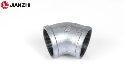
The standard governing these dimensions is ASME B16.11, “Forged Fittings, Socket-Welding and Threaded.” Any reputable manufacturer, such as the makers of these high-quality pipe fittings, produces their components to meet these precise dimensional standards.
Worked Example: A 2-Inch Socket Weld Offset
Let’s plan a small rolling offset using 2-inch, Class 3000 socket weld 45-degree elbows.
Step 1: Find the Standard Take-Off Dimension. We consult the ASME B16.11 standard or a manufacturer’s catalog. For a 2-inch 45-degree socket weld elbow, the standard center-to-bottom-of-socket dimension is 1.125 inches (1 1/8″). This is our “Elbow Center” or take-off.
Step 2: Account for the Socket Depth and Gap. The total socket depth for a 2-inch fitting is typically 0.625 inches (5/8″). We must remember our mandatory 1/16-inch gap. This means the pipe will insert into the socket by a distance of (5/8″ – 1/16″) = 9/16″.
Step 3: Calculate the Pipe Cut-Length. Suppose the center-to-center distance between our two elbows is 36 inches. The calculation is different from the buttweld method.
Cut Length = Center-to-Center – (2 × Take-off) + (2 × Insertion Depth) Cut Length = 36″ – (2 × 1.125″) + (2 × 9/16″) Cut Length = 36″ – 2.25″ + 1.125″ Cut Length = 34.875″ or 34 7/8″
You can see how the logic shifts. We still subtract the fitting’s take-off, but we must add back the portion of the pipe that will be hidden inside the socket. Forgetting to add back the insertion depth is a very common mistake for those new to socket weld fabrication.
Method 3: How to Calculate 45 Degree Elbow Center for Threaded Fittings
Threaded fittings, often made from durable malleable cast iron, are the foundation of many lower-pressure systems. They are ubiquitous in residential and commercial plumbing for natural gas, compressed air, and non-potable water lines. Like socket weld fittings, the pipe joins by entering the fitting, which requires an adjustment to our thinking.
An Introduction to Malleable Iron Threaded Fittings
Threaded connections rely on the mechanical interference of tapered threads. In North America, the NPT (National Pipe Taper) standard is dominant. The pipe has male threads on the outside, and the fitting has female threads on the inside. As you tighten the joint, the tapers wedge together, creating a strong mechanical bond. A thread sealant (like PTFE tape or pipe dope) is required to fill the microscopic voids and make the joint leak-proof. The art of working with malleable iron fittings lies in achieving the correct tightness without damaging the threads or the fitting.
The Concept of Thread Engagement or “Make-Up”
When you screw a pipe into a fitting, the distance it travels is called the “thread engagement” or “make-up.” This distance is not arbitrary. For NPT threads, there is a standard length of effective threads. While the final tightness can vary slightly based on the strength of the installer and the tools used, we can use a standard value for calculation purposes. Failing to account for this make-up will result in pipes that are too short.
Finding the Center and Adjusting for Make-Up
Similar to socket weld, the “how to calculate 45 degree elbow center” question is answered by looking up the standard center-to-face dimension in a table. For threaded malleable iron fittings, the relevant standard is ASME B16.3. The pipefitter’s task is to find this value and then correctly apply the thread engagement to find the cut length.
A Real-World Scenario: A 1-Inch Threaded Gas Line
Let’s imagine we are running a 1-inch black iron pipe for a natural gas line to a new appliance. We need to use two 45-degree elbows to offset around a duct.
Step 1: Find the Standard Take-Off Dimension. We look at the ASME B16.3 chart for a 1-inch, 45-degree threaded elbow. The standard center-to-face dimension is 0.88 inches (approximately 7/8″). This is our take-off value.
Step 2: Determine the Standard Thread Engagement. We consult a pipefitter’s handbook or an NPT standard chart. For a 1-inch NPT pipe, the nominal thread engagement (make-up) is 0.53 inches (just over 1/2″).
Step 3: Calculate the Pipe Cut-Length. Let’s say the required center-to-center distance for our offset is 24 inches. The logic is identical to the socket weld calculation.
Cut Length = Center-to-Center – (2 × Take-off) + (2 × Thread Engagement) Cut Length = 24″ – (2 × 0.88″) + (2 × 0.53″) Cut Length = 24″ – 1.76″ + 1.06″ Cut Length = 23.3″
This would be cut to approximately 23 5/16″. Again, we subtract the fitting’s contribution to the overall length but add back the part of our pipe that disappears into the fitting. This “subtract then add back” logic is the key to working with both socket weld and threaded systems.
Advanced Applications and Professional Insights
Once you have mastered the basic calculations for the three main fitting types, you can begin to appreciate the more subtle aspects of the craft. True expertise is not just about knowing the formulas; it is about knowing how to apply them in complex situations and how to adapt when the real world doesn’t perfectly match the textbook.
The Challenge of the Rolling Offset
A simple offset moves a pipe in one plane (e.g., moving it left while it continues to travel forward). A rolling offset is a more complex and elegant maneuver that moves the pipe in two planes simultaneously (e.g., moving it left and up while it travels forward). The 45-degree elbow is the heart of this technique.
While the calculation for the elbow center itself does not change, determining the length of the “travel piece” (the diagonal pipe between the two elbows) requires an extra layer of trigonometry. You must use the Pythagorean theorem twice. First, you find the diagonal of the base of the triangle formed by the “roll” and “set” dimensions. Then, you use that diagonal as one side of a new triangle with the “travel” as the hypotenuse. While a full explanation is beyond our current scope, it is important to recognize that your mastery of the simple elbow center is the first step toward tackling these advanced layouts.
Field Verification: The “Trust, but Verify” Principle
Standards like ASME are invaluable. They ensure that a 4-inch elbow from one manufacturer will work with a 4-inch elbow from another. However, manufacturing is not a perfect science. There are acceptable tolerances. A fitting might be a few thousandths of an inch off from the book value. In most cases, this is not a problem. But in high-precision jobs or when fabricating many identical pieces, it is a professional best practice to perform a field verification.
Take one fitting from the batch you are using. Place it on a flat steel plate. Use a combination square to physically measure the center-to-face dimension. Compare your real-world measurement to the book value. If there is a slight difference, use your measured value for your calculations. This simple act of verification can prevent the compounding of small errors and ensures a perfect fit.
The Digital Toolbox: The Role of Apps and Calculators
In 2025, no discussion of pipefitting is complete without acknowledging the role of technology. There are dozens of excellent pipefitting calculator apps available for smartphones. These apps can compute offsets, rolling offsets, and fitting take-offs in seconds. They are powerful tools that increase speed and reduce the chance of simple arithmetic errors.
However, a reliance on these apps without a fundamental understanding of the underlying principles is a crutch. What happens when your battery dies? What happens when an unusual fitting is not in the app’s database? How do you know if you have entered the numbers correctly or if the app’s output makes sense? The true professional uses the app as a tool for verification and speed but possesses the foundational knowledge to do the work manually. Understanding how to calculate 45 degree elbow center from first principles is your intellectual backup system.
Frequently Asked Questions (FAQ)
1. What is the easiest formula to remember for a 45-degree buttweld elbow center? For a standard Long Radius (LR) 45-degree elbow, the easiest shortcut is: Center = NPS × 0.6213. For a Short Radius (SR) 45, it is: Center = NPS × 0.4142.
2. Does the elbow center calculation change for galvanized versus black pipe fittings? No. The calculation is based on the fitting’s geometry, which is standardized regardless of the surface finish. A 1-inch threaded malleable iron elbow will have the same take-off dimension whether it is black or has a galvanized zinc coating. The material and finish do not alter the dimensional standards.
3. How do you calculate the “travel” piece in a 45-degree offset? The travel is the length of the diagonal pipe between the two elbows. For a simple offset, the formula is: Travel = Set × 1.414. The “Set” is the perpendicular distance between the centerlines of the two parallel pipes. The number 1.414 is the cosecant of 45 degrees, a standard multiplier for this calculation.
4. Is there a difference between “take-off” and “elbow center”? The terms are often used interchangeably, but there is a subtle distinction. “Elbow center” is a more general geometric term derived from the bend radius. “Take-off” is the practical term for the dimension you subtract from your center-to-center measurement to find your pipe cut length. For buttweld fittings, they are the same. For socket weld and threaded fittings, the take-off is a tabulated center-to-face dimension.
5. Where can I find official tables of pipe fitting dimensions? The primary sources are the standards published by the American Society of Mechanical Engineers (ASME). The key documents are ASME B16.9 for Buttweld Fittings, ASME B16.11 for Forged Socket Weld and Threaded Fittings, and ASME B16.3 for Malleable Iron Threaded Fittings. Many manufacturers and piping supply houses also provide these charts in their catalogs and online.
6. Is the formula for a 90-degree elbow center different? Yes, and it is much simpler. For a 90-degree elbow, the elbow center (or take-off) is equal to its bend radius. So, for a 90-degree LR elbow, the center is 1.5 × NPS. For a 90-degree SR elbow, the center is 1.0 × NPS. The trigonometric calculation (Tan(90/2) × Radius) also works, as Tan(45°) = 1.
Conclusion
The journey from a blueprint’s line to a functional piping system is paved with precision. In this process, the ability to correctly calculate the center of a 45-degree elbow is not a minor detail; it is a cornerstone of the pipefitter’s craft. We have seen that this skill is an elegant blend of simple trigonometry and practical knowledge. It requires an understanding of the fitting’s geometry, a familiarity with industry standards, and a careful consideration of the joining method, whether it be the edge-to-edge union of a buttweld joint or the internal connection of a socket weld or threaded fitting.
To master this calculation is to empower yourself. It grants you the ability to translate abstract dimensions into tangible, perfectly fitting components. It is a guard against waste, a defense against rework, and a testament to your professionalism. While digital tools can aid in speed, the foundational, manual knowledge is what builds confidence and allows for true problem-solving in the field. By embracing the logic behind the formulas, you elevate your work from mere assembly to a form of industrial art, ensuring that every offset you build is accurate, efficient, and strong.
References
American Society of Mechanical Engineers. (2018). ASME B16.11-2018: Forged fittings, socket-welding and threaded. ASME. https://www.asme.org/codes-standards/find-codes-standards/b16-11-forged-fittings-socket-welding-threaded
American Society of Mechanical Engineers. (2018). ASME B16.9-2018: Factory-made wrought buttwelding fittings. ASME. https://www.asme.org/codes-standards/find-codes-standards/b16-9-factory-made-wrought-buttwelding-fittings
Kenyon, W. & Kenyon, B. (2004). Pipe-fitter’s and pipe-welder’s handbook. Pearson Prentice Hall.
Lindsey, J. A. (2015). Pipefitting, level 3 (4th ed., Trainee Guide). Pearson.
R. (2016, June 20). Pipe fitting course lesson 2 how to calculate a 45 degree offset. YouTube. https://www.youtube.com/watch?v=FGFibT13824
Smith, R. (2020). Pipe trades pocket manual. McGraw-Hill Education.
Taylor Forge. (1965). Taylor Forge bulletin 451: Pipe-fitter’s “rule-of-thumb”. Taylor Forge & Pipe Works.
The Engineering ToolBox. (n.d.). Pipes and tubes – dimensions.
United Association. (2010). Pipe Trades Handbook. United Association of Journeymen and Apprentices of the Plumbing and Pipe Fitting Industry of the United States and Canada.
Zappe, R. W. (2004). Valve and piping codes and standards. Gulf Professional Publishing.