
Abstract
Determining the center of a 90-degree elbow is a foundational skill in pipefitting and plumbing, essential for accurate system layout and fabrication. This process involves calculating the “center-to-face” dimension, which is the distance from the fitting’s center point to the face of one of its openings. The calculation varies depending on the elbow’s type, primarily distinguished by its radius: long radius (LR) or short radius (SR). Standardized formulas, derived from the nominal pipe size (NPS), are used to find this dimension. For LR elbows, the center-to-face dimension is 1.5 times the NPS, while for SR elbows, it is equal to the NPS. However, practical application requires accounting for variables such as the fitting connection type (butt-weld, socket-weld, or threaded) and manufacturing tolerances as defined by standards like ASME B16.9 and B16.3. Inaccurate calculation or measurement leads to significant errors in pipe length, causing material waste, increased labor costs, and compromised system integrity. Mastering this calculation is therefore a non-negotiable aspect of professional craftsmanship in piping trades.
Key Takeaways
- The center-to-face for a long radius (LR) 90-degree elbow is 1.5 times the nominal pipe size (NPS).
- The center-to-face for a short radius (SR) 90-degree elbow is equal to the nominal pipe size (NPS).
- Always account for thread engagement, or “take-out,” when working with threaded malleable iron fittings.
- Understanding how to find a 90 degree elbow center is fundamental for accurate pipe cutting and layout.
- Verify calculations against manufacturer specification sheets or standards like ASME B16.9 for precision.
- Inaccurate center measurements are a leading cause of costly material waste and rework on job sites.
Table of Contents
- The Foundation: Why the Elbow Center Is the Heart of the Matter
- Mistake #1: Misapplying Formulas and Ignoring the Radius
- Mistake #2: Overlooking the Nuances of Measurement Technique
- Mistake #3: Disregarding the Impact of Material and Connection Type
- Advanced Scenarios: Beyond the Basic 90-Degree Turn
- Frequently Asked Questions (FAQ)
- A Final Reflection on Precision and Craft
- References
The Foundation: Why the Elbow Center Is the Heart of the Matter
In the world of piping, where fluids and gases are the lifeblood of our industries and homes, precision is not a luxury; it is the bedrock of safety and functionality. Imagine trying to build a skeleton without knowing the exact length of the bones. The result would be a contorted, non-functional form. In much the same way, a piping system is a skeleton of interconnected conduits, and the fittings are its joints. The ability to correctly locate the center of a 90-degree elbow is akin to understanding the pivot point of a joint. It is the single most critical measurement that dictates the length of every straight piece of pipe connected to it. Getting this wrong, even by a small fraction of an inch, can have cascading consequences, turning a well-planned project into a puzzle of misaligned parts. This fundamental concept is where the craft of pipefitting elevates from simple assembly to a technical art form.
Understanding the “Center-to-Face” Dimension
Let us begin by clarifying our central term. When we speak of finding the elbow’s “center,” we are referring to a specific measurement known as the “center-to-face” distance. Picture the 90-degree elbow resting on a flat surface. Now, imagine two lines, each extending straight out from the center of its two openings. These lines will intersect at a point, forming a perfect right angle. This intersection point is the theoretical “center” of the elbow. The center-to-face dimension is the distance from this imaginary center point to the flat face of either opening.
Think of it like this: if the elbow were the corner of a square, the center-to-face dimension would be the distance from that corner to the middle of one of the square’s sides. Because a standard 90-degree elbow is symmetrical, this distance is the same for both openings. This measurement is the key that unlocks the ability to perform accurate “take-offs.” A take-off is the process of subtracting the fitting dimensions from the overall layout measurements to determine the exact cut length of the pipe that will fit between two fittings. Without a correct center-to-face dimension, every pipe cut will be either too long or too short.
The High Cost of Inaccuracy: More Than Just Wasted Pipe
The consequences of failing to correctly determine the center-to-face dimension extend far beyond mere inconvenience. Let’s consider the tangible costs. First is the direct financial loss from material waste. A pipe cut to the wrong length, especially a large-diameter pipe made from an expensive alloy, becomes scrap. In a large-scale industrial project, these “mis-cuts” can accumulate, representing thousands of dollars in wasted material. A study on construction waste indicated that piping and plumbing materials can account for a notable percentage of on-site refuse, much of which is attributable to fabrication errors (Poon et al., 2004).
Second is the cost of labor. Time is spent measuring, cutting, and attempting to fit the incorrect pipe. More time is then lost procuring new material, re-measuring, and re-cutting. This rework not only inflates labor hours but also disrupts the project schedule, potentially causing delays that have their own financial penalties. Finally, there is the cost to the integrity and safety of the system. Forcing a misaligned pipe into place can induce stress on the fittings and welds. In a high-pressure steam line or a pipeline carrying volatile chemicals, such induced stress is a latent failure waiting to happen. It compromises the mechanical strength of the joint and can lead to catastrophic leaks or ruptures down the line. Therefore, learning how to find a 90 degree elbow center is not just about neatness; it’s a core competency for ensuring a robust, reliable, and safe installation.
A Brief Look at Elbow Types: Long Radius vs. Short Radius
Before we delve into the calculations, it is imperative to understand that not all 90-degree elbows are created equal. In the realm of butt-weld fittings, which are common in industrial applications, there are two primary classifications based on the fitting’s curvature: Long Radius (LR) and Short Radius (SR).
A Long Radius (LR) elbow has a curvature radius that is 1.5 times the Nominal Pipe Size (NPS). This creates a gentler, more sweeping turn. LR elbows are the default standard in most piping systems because their gradual bend minimizes pressure drop and reduces turbulence in the fluid flow.
A Short Radius (SR) elbow, by contrast, has a curvature radius that is equal to the Nominal Pipe Size (NPS). This results in a much sharper, more compact turn. SR elbows are typically used in tight spaces where a long radius elbow would not fit or in low-pressure applications where flow characteristics are less of a concern, such as architectural handrails or drain lines.
The distinction is not merely academic; it is the first and most important variable in our calculation. Using the formula for an LR elbow on an SR elbow (or vice versa) will result in a significant error. Imagine you need to make a turn in a hallway. A long radius turn is like a gentle arc, while a short radius turn is like a sharp pivot at the corner. The distance you travel and the space you occupy are vastly different, and the same logic applies to our pipe fittings.
| Feature | Long Radius (LR) 90° Elbow | Short Radius (SR) 90° Elbow |
|---|---|---|
| Curvature Radius | 1.5 x Nominal Pipe Size (NPS) | 1.0 x Nominal Pipe Size (NPS) |
| Center-to-Face Formula | Center = 1.5 x NPS | Center = 1.0 x NPS |
| Primary Advantage | Lower friction loss, less turbulence | Compact size, fits in tight spaces |
| Common Applications | General process piping, high-flow systems | Restricted areas, low-pressure systems |
| Relative Cost | Standard cost | Often slightly less expensive |
| Visual Appearance | More gradual, sweeping bend | Sharper, more abrupt turn |
Mistake #1: Misapplying Formulas and Ignoring the Radius
The most frequent and fundamental error a novice pipefitter makes is applying the wrong mathematical rule to the problem at hand. It is the equivalent of a carpenter using a metric tape measure for a project specified in imperial units. The world of pipe fittings is governed by standards, and these standards provide us with simple, elegant formulas. To ignore them is to invite chaos into your layout. The first step toward mastery is to commit these core formulas to memory and, more importantly, to understand when and how to apply them. This is not about rote memorization alone, but about grasping the geometric logic that underpins these rules.
The Core Principle: The Geometry of a Perfect Turn
At its heart, the calculation for a 90-degree elbow center is a simple application of geometry. As we discussed, the elbow represents a segment of a circle’s arc. The “center” of the elbow is the center of that circle. The center-to-face dimension, therefore, is simply the radius of that circle. The entire system of calculation hinges on one question: What is the radius of the bend?
The industry, through organizations like the American Society of Mechanical Engineers (ASME), has standardized these radii to ensure that a 4-inch LR elbow from one manufacturer is dimensionally interchangeable with a 4-inch LR elbow from another. This standardization is what makes modern piping possible. The formulas are not arbitrary; they are the codified expression of this standardized geometry. When you use the formula, you are not just plugging in numbers; you are invoking a standard that ensures your work will integrate seamlessly with components from a global supply chain, including high-quality malleable cast iron fittings that adhere to these precise specifications.
The Go-To Formula for Long Radius (LR) 90-Degree Elbows
For the vast majority of piping jobs, you will be working with Long Radius (LR) elbows. They are the workhorse of the industry. The formula for the center-to-face dimension of an LR 90-degree elbow is beautifully simple.
Center-to-Face (in inches) = 1.5 × Nominal Pipe Size (NPS)
Let’s break this down. The Nominal Pipe Size (NPS) is a North American set of standard sizes for pipes used for high or low pressures and temperatures. For example, if you are working with a 4-inch pipe, the NPS is 4. To find the center-to-face of a 4-inch LR 90-degree elbow, you would calculate:
Center = 1.5 × 4 inches = 6 inches
This means that from the center of the elbow to the face of the opening, the distance is 6 inches. This is your “take-off” dimension. If your plans show a center-to-center distance of 60 inches between two 4-inch LR elbows, you would subtract the take-off for both elbows (6 inches + 6 inches = 12 inches) from the total distance. The resulting cut length for your pipe would be 60 – 12 = 48 inches.
The Specific Formula for Short Radius (SR) 90-Degree Elbows
While less common, you will inevitably encounter situations that call for a Short Radius (SR) elbow. These are often found in tight mechanical rooms or within skid-mounted equipment where space is at a premium. The formula is just as simple, but critically different.
Center-to-Face (in inches) = 1.0 × Nominal Pipe Size (NPS)
Or, more simply, the center-to-face dimension is the same as the pipe size. Let’s use our 4-inch pipe example again. For a 4-inch SR 90-degree elbow, the calculation is:
Center = 1.0 × 4 inches = 4 inches
Notice the difference? The take-off for the SR elbow is 2 inches shorter than for the LR elbow. If you were to use the LR formula (6 inches) by mistake when you actually had an SR elbow (4 inches), your pipe cut would be off by 2 inches on that end. If you made the same mistake on both ends of the pipe, the pipe would be 4 inches too short, making it completely unusable. This is a clear illustration of how a simple mistake in formula selection leads directly to waste.
A Comparative Table of LR and SR Elbow Center Dimensions
To make this even clearer, let’s visualize the differences across a range of common pipe sizes. This table serves as a quick reference guide and highlights the growing discrepancy between LR and SR dimensions as the pipe size increases. All dimensions are in inches.
| Nominal Pipe Size (NPS) | LR 90° Center-to-Face (1.5 x NPS) | SR 90° Center-to-Face (1.0 x NPS) | Difference |
|---|---|---|---|
| 2″ | 3″ | 2″ | 1″ |
| 3″ | 4.5″ | 3″ | 1.5″ |
| 4″ | 6″ | 4″ | 2″ |
| 6″ | 9″ | 6″ | 3″ |
| 8″ | 12″ | 8″ | 4″ |
| 10″ | 15″ | 10″ | 5″ |
| 12″ | 18″ | 12″ | 6″ |
As the table demonstrates, the potential for error is not static; it scales with the size of the pipe. A 1-inch error on a 2-inch line might be manageable (though still unprofessional), but a 6-inch error on a 12-inch line is a major problem, both financially and logistically.
Mistake #2: Overlooking the Nuances of Measurement Technique
Knowing the correct formula is only half the battle. The other half lies in the physical act of measurement and marking. It is in this translation from theoretical number to physical mark on a piece of steel that a second category of costly mistakes arises. A craftsperson can have the correct formula in their head but fail to apply it accurately in the real world due to sloppy technique or a misunderstanding of how different fitting types affect the final measurement. Precision in thought must be matched by precision in action. This involves using the right tools, understanding the concept of “take-out” for different fittings, and applying a consistent, repeatable method.
The Step-by-Step Method for Finding the Center
Let’s walk through the physical process of laying out a cut for a pipe that will connect to a 90-degree elbow. Assume we are connecting to a 6-inch LR elbow.
- Calculate the Take-off: First, apply the formula. For a 6-inch LR 90, the take-off is 1.5 × 6 = 9 inches. This is the dimension you must commit to memory for this step.
- Establish the Centerline: Your construction drawings will show the centerlines of your pipes. On the floor or a workbench, use a chalk line or a long straightedge to mark the centerline of the pipe run leading into the elbow and the centerline of the pipe run leaving the elbow. These two lines should meet at a perfect 90-degree angle. The point where they intersect is your theoretical center point.
- Mark the Fitting Allowance: From the intersection point, measure back along each centerline a distance equal to your calculated take-off. In our 6-inch elbow example, you would measure back 9 inches along each line and make a clear mark. These marks represent where the faces of your elbows will be.
- Determine the Cut Length: The distance between these two new marks (one on the incoming pipe’s centerline, one on the outgoing’s) is not your pipe length. The cut length of the pipe is the center-to-center distance between the fittings minus the sum of the take-offs. For a simple straight run between two elbows, if the center-to-center distance is 80 inches, the pipe cut length is 80 – (9 + 9) = 62 inches.
This methodical approach removes guesswork. Every mark has a purpose, and every measurement is derived from the initial calculation.
Tools of the Trade: Beyond the Tape Measure
While a quality tape measure is indispensable, a professional relies on a suite of tools to ensure accuracy.
- Combination Square: This is essential for ensuring your markings are perfectly square to the pipe’s end and for transferring lines accurately around the pipe’s circumference.
- Wraparound: A flexible, heat-resistant tool used to draw a straight line around the full circumference of a pipe for cutting. It ensures the cut is perfectly perpendicular to the pipe’s axis.
- Center Finder: A specialized tool that helps you quickly and accurately locate the center point of a pipe’s end.
- Level: Both a standard spirit level and a torpedo level are needed to ensure pipes are installed perfectly horizontally (level) or vertically (plumb).
Using these tools correctly is a skill in itself. A hurried measurement with a tape measure hooked carelessly on an edge can introduce an error of 1/16th or 1/8th of an inch. While seemingly small, these errors accumulate over a long run of pipe, resulting in significant misalignment at the final connection point.
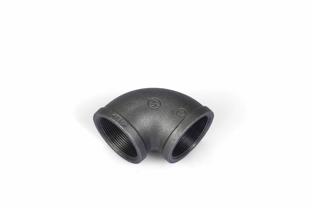
Accounting for Thread Engagement in Malleable Iron Fittings
The discussion so far has centered on butt-weld fittings, where the pipe and fitting are welded edge to edge. However, a vast amount of piping, particularly in plumbing, gas, and fire protection systems, uses threaded fittings, such as those made from malleable cast iron or galvanized steel. Here, we encounter a new and critical variable: thread engagement, also known as “take-out” or “screw-in.”
When you screw a pipe into a threaded fitting like a malleable iron elbow, the pipe does not butt up against a hard stop inside. It threads in until a tight seal is formed. The distance the pipe actually enters the fitting is the thread engagement. The center-to-face dimension of the fitting is a fixed value, but to find the true cut length of the pipe, you must subtract this engagement distance from the fitting’s allowance.
The calculation looks like this: Effective Take-off = Center-to-Face of Fitting – Thread Engagement
Unfortunately, there is no universal formula for thread engagement. It depends on the pipe size, the specific thread standard (e.g., NPT – National Pipe Taper), and how tightly the fitter tightens the joint. However, manufacturers and piping handbooks provide standard charts for these dimensions. For example, for a 2-inch NPT threaded pipe, the standard thread engagement is approximately 3/4 of an inch.
Let’s imagine you are using a 2-inch threaded malleable iron 90-degree elbow. You look up the manufacturer’s data and find its center-to-face dimension is 2.38 inches. You know the standard thread engagement for 2″ NPT is about 0.75 inches.
Your effective take-off is 2.38″ – 0.75″ = 1.63 inches (or 1 5/8″).
This is the number you must use to calculate your pipe cut length. Ignoring thread engagement is a classic beginner’s mistake that guarantees your threaded pipe system will not fit together as planned.
A Practical Example: Laying Out a Simple Offset
Let’s solidify this with a thought experiment. You need to install a simple horizontal offset using two 4-inch LR 90-degree elbows. The plans show the two parallel pipe runs must be 24 inches apart, center to center. The question is, what is the cut length of the diagonal pipe connecting the two elbows? This is a classic “45-degree offset” problem that uses two 90-degree elbows.
- The Geometry: The offset creates a right-angled triangle. The “set” and “run” of the triangle are both 24 inches (the distance between the pipe centerlines). The diagonal pipe is the hypotenuse.
- Calculate the Hypotenuse: Using the Pythagorean theorem (a² + b² = c²) is cumbersome. Pipefitters use a constant: for a 45-degree offset, the travel (hypotenuse) is the set (24 inches) times 1.414. Travel = 24″ × 1.414 = 33.936 inches. Let’s call it 33 15/16 inches. This is the center-to-center distance between your two elbows.
- Calculate the Take-off: We are using 4-inch LR 90s. The take-off for one elbow is 1.5 × 4 = 6 inches. Since we have two elbows, the total take-off is 6 + 6 = 12 inches.
- Determine the Cut Length: Now, subtract the total take-off from the calculated travel distance. Cut Length = 33 15/16″ – 12″ = 21 15/16 inches.
This is the precise length to which you must cut your 4-inch pipe. Every step in this process was dependent on the initial, correct calculation of the elbow’s center-to-face dimension.
Mistake #3: Disregarding the Impact of Material and Connection Type
A pipefitter who has mastered the formulas and measurement techniques can still be undone by the third major type of error: failing to account for the physical realities of the components themselves. Fittings are not abstract geometric shapes; they are manufactured objects made from specific materials and designed for specific connection methods. A butt-weld elbow, a socket-weld elbow, and a threaded elbow, even if all are 2-inch 90-degree fittings, have different dimensional considerations. Believing that a single “take-off” number applies universally across all types is a direct path to costly fabrication mistakes. A true craftsperson develops a feel for the materials and an appreciation for the manufacturing standards that govern them.
Butt-Weld vs. Socket-Weld vs. Threaded Fittings: How the Center Changes
Let’s compare the three most common connection types and how they influence our calculations.
- Butt-Weld (BW) Fittings: These are the fittings we have primarily discussed. They are designed to be welded directly, edge-to-edge, to the pipe. The dimensions for standard BW fittings are governed by ASME B16.9. For these fittings, the center-to-face formula (e.g., 1.5 x NPS for LR 90) is a direct application. The face of the fitting is the point of measurement.
- Socket-Weld (SW) Fittings: These fittings have a recessed area (a socket) into which the pipe is inserted before being welded around the outside. The dimensions are governed by ASME B16.11. The pipe does not bottom out in the socket; a mandatory 1/16-inch gap is left at the base of the socket to prevent the weld from cracking due to thermal expansion. This gap must be factored into your calculation. The take-off calculation involves the center-to-face dimension of the fitting minus the depth of the socket, plus the 1/16-inch expansion gap. This complexity means relying on manufacturer’s charts is not just helpful, it is essential.
- Threaded Fittings: As previously detailed, these fittings, governed by standards like ASME B16.3 for malleable iron, require subtracting the thread engagement from the center-to-face dimension. The center-to-face dimension itself is a standard value, but the effective take-off for the pipe cut is a derived number. Materials like the malleable cast iron used in Jianzhi fittings are specifically engineered for this purpose, providing the strength to handle the stresses of threaded connections (Jianzhi Pipe Fittings, n.d.).
This table summarizes the key differences in approach:
| Fitting Type | Governing Standard (Example) | Key Calculation Factor | Level of Complexity |
|---|---|---|---|
| Butt-Weld (BW) | ASME B16.9 | Direct center-to-face dimension | Low |
| Socket-Weld (SW) | ASME B16.11 | Center-to-face minus socket depth, plus expansion gap | Medium |
| Threaded | ASME B16.3 (Malleable Iron) | Center-to-face minus thread engagement | High |
The Unique Case of Malleable Cast Iron Fittings
Malleable cast iron is a fascinating material with a long history in piping. It starts as brittle cast iron, which is then heat-treated in a process called annealing. This process changes the material’s microstructure, making it “malleable” – tougher and more ductile, able to withstand the pressures and vibrations of a piping system without fracturing (Jianzhi Pipe Fittings, 2023). This makes it ideal for threaded fittings.
When you are working with galvanized pipe fittings or black iron malleable fittings, you are almost always dealing with NPT or BSPT threads. The precision of these fittings is paramount. The manufacturer must hold tight tolerances not just on the center-to-face dimension but also on the taper, depth, and starting point of the threads. A poorly made fitting will either not allow the pipe to engage far enough to create a seal or allow it to screw in too far, throwing off the layout. This is why sourcing fittings from established manufacturers who adhere to international standards is a crucial aspect of risk management for any piping project. The reliability of your take-off calculation for a threaded system is directly proportional to the quality and dimensional consistency of the fittings you are using.
How Manufacturing Standards (ASME, EN) Impact Dimensions
We have mentioned standards like ASME B16.9 and EN 10253, but what do they actually do? These documents are the rulebooks for the entire industry. They specify everything about a fitting:
- Material composition and strength.
- Dimensions and tolerances (including center-to-face).
- Marking requirements (what information must be stamped on the fitting).
- Testing procedures.
These standards are what ensure a 6-inch LR 90 elbow bought in Texas will fit a pipe system designed in Germany using a fitting from a Chinese manufacturer like Jianzhi, which produces fittings to multiple standards including ANSI and BS (Jianzhi Pipe Fittings, n.d.).
The important lesson here is that while our formulas (1.5 x NPS) are excellent rules of thumb, the ultimate source of truth is the standard itself or the manufacturer’s catalog that is certified to that standard. For critical applications or non-standard fittings, a professional pipefitter will always have these charts on hand. The formula is a starting point; the standards are the final arbiter. A helpful resource can be found in a detailed Elbow center calculation formula, which often aligns with these published standards.
Verifying Dimensions: When to Trust the Chart and When to Measure
This leads to a final point of craftsmanship: the habit of verification. While standardized fittings are remarkably consistent, manufacturing is not perfect. In highly critical work, or if you are using fittings from an unknown source, it is wise to physically measure a sample fitting yourself.
Place the elbow on a flat, level surface. Use a combination square or two framing squares to create a physical intersection point for the centerlines. Measure from this point to the face of the fitting. Does your measurement match the chart? If it is off by a small, consistent amount, you may need to adjust your take-off number for that batch of fittings. This act of verification builds confidence and catches potential problems before they are multiplied across dozens of pipe cuts. It is the difference between blindly trusting the system and actively engaging with it as a skilled professional. This empirical check, as supported by engineering principles, provides a final layer of quality assurance to the fabrication process (Mian, 2018).
Advanced Scenarios: Beyond the Basic 90-Degree Turn
Once you have achieved fluency with the fundamentals of the 90-degree elbow, you can begin to tackle more complex geometric challenges. The principles remain the same, but they are applied in three-dimensional space or to different angles. Mastering these advanced scenarios is what separates a competent pipefitter from a true master of the craft. These situations require not just knowledge of formulas, but a strong ability to visualize the piping system in three dimensions.
Calculating for Rolling Offsets
A rolling offset is one of the most common complex configurations. Unlike a simple offset that travels along a single plane (horizontally or vertically), a rolling offset changes position in two planes simultaneously. It moves up (or down) while also moving left (or right).
Imagine a pipe running along a wall that needs to jog over to an adjacent wall while also rising to a higher elevation. The connecting piece is a rolling offset. While it may look intimidating, it is simply two right-angled triangles combined.
- Identify the Dimensions: You will have a “set” (the horizontal change), a “roll” (the vertical change), and a “run.”
- Calculate the True Offset: First, you use the Pythagorean theorem to find the true diagonal of the offset in the plane of the roll. True Offset = √(Set² + Roll²).
- Calculate the Travel: Now you have a new right-angled triangle with the “run” and the “true offset” as its two legs. The travel piece (the hypotenuse) is calculated as: Travel = √(Run² + True Offset²).
- Apply the Take-off: This calculated “Travel” is the center-to-center distance between your fittings. From here, the process is familiar. You subtract the take-off for the two fittings at either end to find the exact cut length of your pipe.
The key is to break the complex 3D problem down into manageable 2D triangles. The take-off calculation for the 90-degree elbows used in the roll remains the same simple formula we have already mastered.
Working with Odd-Angle Elbows (e.g., 45 degrees)
Piping systems are not limited to 90-degree turns. 45-degree elbows are extremely common, and other angles like 22.5 degrees or 60 degrees are also used. Does our formulaic approach still work? Yes, but it requires a new constant derived from trigonometry.
The formula for the center-to-face dimension of any butt-weld elbow is: Center = tan(Angle / 2) × Radius
Let’s test this. For a 90-degree elbow: Angle / 2 = 45 degrees. The tangent of 45 degrees is 1. Center = 1 × Radius. For an LR elbow, the Radius is 1.5 × NPS. So, Center = 1 × (1.5 × NPS), which is our original formula. It works.
Now, let’s apply it to a 45-degree LR elbow: Angle / 2 = 22.5 degrees. The tangent of 22.5 degrees is approximately 0.4142. The Radius is still 1.5 × NPS. So, the Center-to-Face for a 45-degree LR elbow is: Center = 0.4142 × (1.5 × NPS)
This is cumbersome. For common angles, pipefitters memorize the constants. The standard take-off for a 45-degree elbow is often listed in charts, but the most common rule of thumb is: Take-off for 45° LR Elbow ≈ 5/8 × NPS
Let’s check this for a 10-inch pipe: 5/8 × 10 = 6.25 inches. Using the tangent formula: 0.4142 × (1.5 × 10) = 0.4142 × 15 = 6.213 inches. The rule of thumb is remarkably close and perfectly adequate for most fieldwork. The principle is that the geometry is consistent, and whether you use a precise trigonometric function or a trusted industry heuristic, you are still calculating the same essential dimension.
The Role of Gaskets in Flanged Elbows
Another layer of complexity is introduced with flanged connections. Flanged elbows do not weld or thread directly to the pipe. Instead, they have flat, drilled plates (flanges) that bolt to a matching flange welded onto the end of the pipe. The seal between the two flanges is made by a gasket.
This introduces two new variables into your calculation:
- The Gasket Gap: The thickness of the gasket creates a space between the two flange faces. Standard gasket thicknesses are typically 1/16 or 1/8 of an inch. This gap must be added to your calculation.
- Flange Type: The center-to-face dimension of a flanged elbow is measured from the center to the face of the flange where the gasket sits. For “raised face” (RF) flanges, this is straightforward. For “ring-type joint” (RTJ) flanges, the dimension is measured to the center of the ring groove, which requires careful consultation of ASME B16.5 standards.
When calculating the cut length for a pipe that will be welded to a flange, your total take-off for one end is: Total Take-off = (Center-to-Face of Flanged Elbow) + (Half of the Gasket Gap)
You only account for half the gasket gap at each end, as the full gap exists between the two fittings. Forgetting the gasket gap is a common error that will result in a pipe that is slightly too long, preventing the flanges from bolting up correctly.
Determining the center of a 90-degree elbow is one of the most essential skills in pipefitting, welding, plumbing, and industrial fabrication. If you miscalculate this measurement, it can lead to wasted material, unnecessary labor costs, and poorly fitting piping systems.
In this guide you’ll learn how to accurately find the elbow center, the differences between long and short radius elbows, and three costly mistakes to avoid — so your installations are precise and professional.
What Is the “Elbow Center” and Why It Matters
When pipefitters talk about the center of a 90-degree elbow, they are referring to the center-to-face dimension — the distance from the imaginary center point of the elbow’s arc to the face of the fitting.
This measurement is the basis for calculating take-off — the amount of pipe you need to cut to fit between two fittings. If this number is wrong, every connected pipe will be either too long or too short.
Long Radius vs Short Radius 90° Elbows
There are two main types of 90-degree elbows used in piping systems:
📌 Long Radius (LR) Elbow
- Center-to-face = 1.5 × Nominal Pipe Size (NPS)
- Provides a gentler bend with smoother flow
- Common in process piping and systems where pressure loss matters
Example: A 4″ LR elbow has a center-to-face of 6″ (1.5 × 4).
📌 Short Radius (SR) Elbow
- Center-to-face = 1.0 × NPS
- Compact, ideal for tight spaces
- Often used where precise flow characteristics are less critical
Example: A 4″ SR elbow has a center-to-face of 4″.
| Elbow Type | Center-to-Face Formula | Best Use |
|---|---|---|
| LR 90° | 1.5 × NPS | Standard piping |
| SR 90° | 1.0 × NPS | Tight spaces |
Step-by-Step: How to Find the Elbow Center
Here’s a professional workflow for accurate layout and cutting:
- Determine Take-Off – Apply the correct formula based on elbow type.
- Mark Pipe Centerlines – Extend chalk lines or draw centerlines for both pipe runs.
- Locate the Center Point – Find where the two centerlines intersect at a 90° angle.
- Measure and Mark – From the center point, measure back the take-off distance and mark the pipe faces.
- Calculate Cut Length – Subtract total take-off from the center-to-center distance between fittings.
This process ensures cuts are accurate and fittings align perfectly.
3 Costly Mistakes to Avoid
❌ Mistake #1: Using the Wrong Formula
Confusing LR and SR formulas leads to wrong pipe lengths, material waste, and rework. Always match the formula to the elbow type.
❌ Mistake #2: Poor Measurement Technique
Having the right number isn’t enough — if you mark or measure poorly, errors still happen. Use proper tools (combination squares, chalk lines, wraparound markers) and double-check marks.
❌ Mistake #3: Ignoring Connection Type
Threaded, socket-weld, and butt-weld fittings all change the effective take-off due to thread engagement or socket depth. Always verify manufacturer specs or standards (e.g., ASME B16.9/B16.11) for accuracy.
Tips for Accurate Field Work
- Use accurate tools: quality tape measures, combination squares, and wraparounds reduce error.
- Account for threads & sockets: This changes the effective length of pipe needed.
- Verify with specs: Always check manufacturer data sheets before final cuts.
Frequently Asked Questions (FAQ)
What is the standard formula for a 90-degree elbow center?
For a standard Long Radius (LR) 90-degree elbow, the formula is: Center-to-Face = 1.5 × Nominal Pipe Size (NPS). For a Short Radius (SR) 90-degree elbow, the formula is: Center-to-Face = 1.0 × Nominal Pipe Size (NPS).
Does the elbow center formula change for different pipe sizes?
No, the formula (the multiplier) remains the same. The result of the calculation changes because the Nominal Pipe Size (NPS) variable changes. For example, the multiplier for an LR 90 is always 1.5, whether it’s a 2-inch pipe or a 24-inch pipe.
How do I find the center of a 45-degree elbow?
The take-off for a 45-degree elbow is different. A common and reliable rule of thumb for a Long Radius (LR) 45-degree elbow is to multiply the Nominal Pipe Size (NPS) by 5/8 (or 0.625). For a 4-inch LR 45, the take-off would be approximately 4 × 5/8 = 2.5 inches.
What’s the difference between a long radius and short radius elbow?
A long radius (LR) elbow has a gentler, wider sweep with a bend radius of 1.5 times the pipe’s nominal size, which is better for flow. A short radius (SR) elbow has a sharp, tight turn with a bend radius equal to the pipe’s nominal size, used mainly in tight spaces.
Is the center-to-face measurement the same for all manufacturers?
For fittings made to a specific standard (like ASME B16.9), the center-to-face dimension should be identical within a very small tolerance, regardless of the manufacturer. This ensures interchangeability. However, for non-standard or specialty fittings, dimensions can vary significantly.
How does wall thickness affect the elbow center calculation?
For standard butt-weld elbow calculations, the wall thickness (or “schedule”) of the pipe does not directly affect the center-to-face dimension. This dimension is based on the nominal pipe size and the centerline of the fitting. However, wall thickness is critical for welding procedures and for the overall strength of the system.
Can I use the same formula for PVC and malleable iron elbows?
No, you should not assume the formulas are the same. PVC fittings (often socket-style) and threaded malleable iron fittings have different standards and connection methods. Butt-weld formulas are for butt-weld fittings. For threaded or socket fittings, you must always consult the manufacturer’s specific data sheets for the correct center-to-face dimensions and then account for socket depth or thread engagement.
A Final Reflection on Precision and Craft
The ability to find the center of a 90-degree elbow, in all its variations, is more than a technical skill. It is a reflection of a deeper commitment to the principles of craftsmanship. It represents an understanding that small details have large consequences, that preparation prevents poor performance, and that a foundation built on precision and knowledge is one that will endure. In the complex network of pipes that underpins our modern world, every joint, every weld, and every measurement is a testament to the skill of the hands that made it. To calculate a take-off correctly is to honor that tradition of excellence, ensuring that the systems we build are not only functional but also safe, efficient, and lasting. It is the quiet, methodical application of these fundamental rules that transforms a collection of pipes and fittings into a reliable and elegant system.
References
Jianzhi Pipe Fittings. (n.d.). Malleable iron pipe fittings. Retrieved May 15, 2025, from
Jianzhi Pipe Fittings. (2023, July 12). Malleable cast iron pipe fittings – The durable and versatile solution for plumbing systems. Jianzhi Pipe Fitting. https://www.jianzhipipefitting.com/2023/07/12/malleable-cast-iron-pipe-fittings-the-durable-and-versatile-solution-for-plumbing-systems/
Mian, M. A. (2018). Project economics and decision analysis: Probabilistic models (Vol. 2). PennWell Books.
Poon, C. S., Yu, A. T. W., & Jaillon, L. (2004). Reducing building waste at construction sites in Hong Kong. Construction Management and Economics, 22(5), 461-470.
American Society of Mechanical Engineers. (2018). Factory-made wrought buttwelding fittings (ASME B16.9-2018). https://www.asme.org/codes-standards/find-codes-standards/b16-9-factory-made-wrought-buttwelding-fittings
American Society of Mechanical Engineers. (2019). Malleable iron threaded fittings: Classes 150 and 300 (ASME B16.3-2019). https://www.asme.org/codes-standards/find-codes-standards/b16-3-malleable-iron-threaded-fittings-classes-150-300
American Society of Mechanical Engineers. (2020). Pipe flanges and flanged fittings: NPS 1/2 through NPS 24 metric/inch standard (ASME B16.5-2020).
European Committee for Standardization. (2021). Butt-welding pipe fittings – Part 1: Wrought carbon steel for general use and without specific inspection requirements (EN 10253-1:2021).